Hello everyone,
I couldn't login for some reason so I had to re-register.
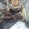
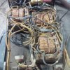
I have an old (very old) pallet lift battery charger that I think is overcharging the batteries and took it apart to see what's going on inside and couldn't find how the charger knows that the batteries are charged. It basically has transformers, circuit board, contactor, a fuse (T-Tron JJN-80) , a breaker and a charge gauge.
In general, what kind of sensing devices are used with theses kind of chargers.
Thanks
Kal
Hi Kal-B (Kal-A),
All batteries are best charged by the correct voltage and current profile, but lead acid batteries are fairly tolerant compared to other batteries.
In automobiles, for example, the battery is charged with a current limit of whatever the alternator can pump out, normally 40 amps to 120 amps, and at a maximum voltage of around 14.6V.
So, what happens in a car is that the battery gets discharged by the huge current taken by the starter motor, 300 to 1,000 amps, which causes the battery voltage to drop, but once the engine fires up, the alternator fairly quickly replenishes the lost charge.
When the battery voltage recovers to 14.6V the alternator maintains that voltage and the battery takes comparatively little current, perhaps 2A.
When the battery is charged and the engine is running, the battery essentially serves no purpose, because all the car electrical equipment is supplied by the alternator.
So that is how the majority of lead acid batteries are charged, not perfectly.
There is another type of charger, which sounds like the one you mention, that just keeps charging regardless of the battery voltage. If the charge current is fairly low this approach will be sort of OK, but if the current is high it will boil the battery.
With the uncontrolled chargers you are expected to time the charge. I used to work in a garage part time and they had a monster battery charger that was uncontrolled. It put out about 40A and would give your battery a good boiling if you forgot to disconnect it in time.
The solution is to incorporate a voltage limiter, of around 14.6V, on your charger.
The other approach would be to just use a switch mode power supply set to 14.6V, to charge your batteries. Switch mode power supplies are available from eBay and Aliexpress for a reasonable price.
spec

")