Continue to Site

Welcome to our site!

Electro Tech is an online community (with over 170,000 members) who enjoy talking about and building electronic circuits, projects and gadgets. To participate you need to register. Registration is free. Click here to register now.

  • Welcome to our site! Electro Tech is an online community (with over 170,000 members) who enjoy talking about and building electronic circuits, projects and gadgets. To participate you need to register. Registration is free. Click here to register now.

How Do You Mount Your Power Strips?

Status
Not open for further replies.
Hi,

Yeah i guess a thicker board would do it. I'd have to see if the distance it would bring the strip out from the wall would bother anything in front of it. I could probably live with 1/4 inch but 3/4 inch would be pushing it.

3/16" board maybe, fender washer maybe, all depends on room you have. Back leg of a table out of the way for computer hardware. Piece of Aluminum might work too. Depend s on what you got kicking around the shop/garage.

Lots of ways to skin a cat.
 
3/16" board maybe, fender washer maybe, all depends on room you have. Back leg of a table out of the way for computer hardware. Piece of Aluminum might work too. Depend s on what you got kicking around the shop/garage.

Lots of ways to skin a cat.

Hi,

Yes, and this is going behind a piece of furniture that is best as close to the wall as possible.

I am kicking another idea around too now.
 
Hi,

Yes, and this is going behind a piece of furniture that is best as close to the wall as possible.

I am kicking another idea around too now.

I don't know exactly what you are doing, but I picture a couple of strips filled with walwarts and 120V plugs for a variety of computer hardware.

Picture a DIN rail with a couple of Low Power DC supplies and a host of TB's , cut off all those AC plugs, add ferrules and fill in TB's . You can get non touch TB's if you are concerned about expose or perhaps a cover to prevent a dog's nose or something. food for thought.

Hi again,

Well for this thread i am concentrating on just mounting the power strip as that is what i really want to do and this may involve more than one in different locations, and possibly for other people i know too who wont want to do any real electrical work. A good idea for those that do however.

I was kicking around another idea which i checked into just a little while ago. I'll say more about that in the next post and see what you think, good or bad.
 
Hello gain,

I was kicking another idea around but just got to look into it a little while ago.

One of the problems i saw was that when i put a molly bolt into the drywall the screw head can be made to stick out as far as i need, 1/8 inch, 1/4 inch etc., to get any distance out from the wall so that i can then hang the power strip on the screw head(s).
What's the MAIN problem with this if i want a nice sturdy power strip mounting?
The main problem is that once the power strip is applied to the screw(s), i can no longer access the screw heads for tightening.

A way around this i am thinking is to drill a hole right through the power strip, from back to front, so that a somewhat narrow screwdriver blade can be inserted right through the front of the power strip and therefore allow tightening even after the power strip is mounted.
This has to work well i think because then i can tighten it good from the front, before anything is plugged in including the strip itself.

Now a question that comes up is, will the hole bother anything, because in some cases it has to go right between the internal power rails.
I dont have the answer for every power strip ever made yet, but i do see that one of my power strips will allow this without hurting anything inside. That's a smaller one where i can look into the holes in the back and see right through to the front plastic of the strip. I can see that by drilling a hole from the back, it would go through the front and thus allow a screwdriver to be inserted into the now new front hole and allow tightening. This will definitely work.
However, the other one, the one i was most hoping to use, does not show a clear path to the front like the smaller one did. Thus i can not be sure yet what the drill bit will hit if a hole is drilled through from the back. The problem is, it has an internal plastic sheet that acts like a second back plate where it stop anything from going in too far. It may still work, but i have to take it apart to find out.
I am guessing this will work but i have to unplug everything and take it apart to find out so i am still thinking about that.
What i see though is that the only mod will be a hole in the front and a hole in that secondary back 'panel'. It will be a small diameter though only maybe 3/16 inch diameter. I dont need a giant screwdriver to fit, just a medium size should do just fine.

Comments welcome.
 
Not sure I follow everything you got in the plan.

Q:

1: What are the devices getting 120V power? qty?

2: 3/16" is pretty big, you could go smaller, different material vs a carbon steel screw/bolt. Not like this is high strength application.

3: Mount a thin plate between studs in wall to build upon. 16" centers

4: drilling Power strips , not sure I do that unless you are with tossing them afterwards to replace.

5: Visual aspect is important? you plan to plug and unplug often?

Over coffee, perhaps it will be more clear.
 
The main problem is that once the power strip is applied to the screw(s), i can no longer access the screw heads for tightening.

I refer you to my previous post, which cures those problems - and in a perfectly safe manor, modifying the power strip is fraught with potential dangers, and probably in breach of legislation?.
 
US power strips usually run 3 bare wires down the length of the strip, connecting to each socket as they pass by. The hot and neutral conductors are offset to each side, with the ground running down the center.

If you drill through one of these, at best you severe the ground conductor. At worst, the ends of the severed ground wire short to hot or neutral if not both.

I think you'll find a description of this idea here.
 
Here's a couple of pictures showing how I fasten them securely, without damaging them at all.

In both cases the sockets are fastened to the 'wall' using two screws that the keyholes slide over, I adjust the screw depths to make them reasonable snug.

The first picture is a brick wall, with wall plugs for the screws, and has a scrap of wood screwed over the top of with just one wall plug and screw, preventing the socket moving upwards and coming off the keyhole screws. As you can see in the picture it was just a rough off-cut that was lying around.

The second is fastened to a piece of MDF board from an old piece of furniture, there's a bank of three screwed to it, for the computer area in my workshop. In this case (as it's fastened to wood) there's two screws driven in over the top at 45 degrees, each screw is above the keyhole mounting points - although one screw midway between them would probably be enough. On bare brick or block you can also do the 45 degree trick, just drill a hole or two over the top at 45 degrees, and insert plugs and screws.

As the wall in question here is plasterboard (dry wall), then assuming it uses wooden uprights?, if you position the midpoint of the keyholes over the upright you can simply drive one 45 degree screw in to lock it in place.

Strip1.png
Strip2.png
 
US power strips usually run 3 bare wires down the length of the strip, connecting to each socket as they pass by. The hot and neutral conductors are offset to each side, with the ground running down the center.

If you drill through one of these, at best you severe the ground conductor. At worst, the ends of the severed ground wire short to hot or neutral if not both.

I think you'll find a description of this idea here.

Wow, that's quite judgmental seeing as how you only know what the guts of ONE power strip looks like.
You should take a few modern ones apart, especially the 10 dollar or less type.
 
Not sure I follow everything you got in the plan.

Q:

1: What are the devices getting 120V power? qty?

2: 3/16" is pretty big, you could go smaller, different material vs a carbon steel screw/bolt. Not like this is high strength application.

3: Mount a thin plate between studs in wall to build upon. 16" centers

4: drilling Power strips , not sure I do that unless you are with tossing them afterwards to replace.

5: Visual aspect is important? you plan to plug and unplug often?

Over coffee, perhaps it will be more clear.

Hi,
1. What difference does it make what devices they are?
2. Yes 1/8 inch is good enough.
3. Dont want a plate.
4. You dont drill randomly placed holes.
5. Semi important.
 
I refer you to my previous post, which cures those problems - and in a perfectly safe manor, modifying the power strip is fraught with potential dangers, and probably in breach of legislation?.

Hi,

1/8 inch holes, it would look like they belong there.

I'll see if i can post a pic or two.
 
Hello again,

I checked one of the power strips a little better. This one has isolated chambers for where the screw holes are, and so the plug connectors are in another chamber. For that strip the 'holes' would work but some of the other strips i have would have to be taken apart to tell.
So this may not work for all power strips, just some.

I still like Nigel's idea of using a third screw on top to keep it from pulling up and off of the other two screws in the wall.
 
I still like Nigel's idea of using a third screw on top to keep it from pulling up and off of the other two screws in the wall.

I've done it a LOT - including where I used to work, where we had huge number of them installed.

Basically it was a TV showroom, so needed LOT'S of sockets for all the TV's, DVD's etc.

The trick is to mount them on wood, either to the shop fittings (which I also installed) where we could, or if you had to fit them on the walls then fasten a piece of wood or MDF to the wall first, and screw to that. As the sockets were in banks or bays, you could fit multiple ones on a piece of MDF, then screw that to the wall with four wall plugs and screws.
 
Wow, that's quite judgmental seeing as how you only know what the guts of ONE power strip looks like.
You should take a few modern ones apart, especially the 10 dollar or less type.

Did I say I've only had one power strip apart? I don't recall saying that. I've had a number of them apart. But if you don't believe me, go ahead an drill through from the top. I'd suggest plugging the drill into the power strip when you do so so you'll know instantly if you've screwed up.
 
Did I say I've only had one power strip apart? I don't recall saying that. I've had a number of them apart. But if you don't believe me, go ahead an drill through from the top. I'd suggest plugging the drill into the power strip when you do so so you'll know instantly if you've screwed up.

Hi,

He he, dont get your panties in a bunch now over this :)

You are saying that you have a number of them apart, and that's very good, good to hear.
However, your consensus is still based on a sample set that is too small. How do i know this? Because you are implying, rudely i might add, that every power strip will be damaged to the point where it wont be usable anymore, and that it would be stupid to do such a thing, all even after i ALREADY SAID that i have one right here in front of me that has CLEAR path from the back to the front without hitting ANYTHING whatsoever.
So your sample set is missing as a minimum, ONE power strip, and that is the one right here before me.
I was going to take a pic, but it would be hard to see. Maybe a drawing would be better that shows the two chambers.

I have taken a few different types apart too, and NONE of them have THREE wires running down the middle.
Maybe we have different power strips? There are a lot of different makes and models.
I did have one a long time ago that was WIRED similar to how you say, but i am not sure what happened to it over the years. It was small but was made of metal not plastic. It had a rocker switch and fuse, not a breaker like the other ones i have.

Because of your reply though i will be extra careful and as i said, once i get it apart i will know right away if this can be done with that particular power strip or not. The one i have right in front of me now though is clear that it would work just fine. Too bad that's not the one i want to use though :)

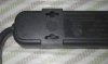
I'll take a pic in a minute or two...

Ok, check out the back of that one.
With this one you could be screws front to back and they would not hit anything because those holes are in separate chambers from the electrical part.
 

Attachments

  • PowerStrip-02.jpg
    PowerStrip-02.jpg
    47.2 KB · Views: 83
  • PowerStrip-01.jpg
    PowerStrip-01.jpg
    52.6 KB · Views: 77
Last edited:
I have one larger one like that, but my 'regular' ones dont have that flange. Thus i'd like to do them too and hopefully get as much strength as the one with the flanges. The one with the flanges was like 35 dollars (USD) the ones without are like 5 dollars each.

Why not then cut some sheetmetal as wide but longer than the strip and epoxy it to the back of the ones without a flange, to make a flange.
 
Hi,

I have one larger one like that, but my 'regular' ones dont have that flange. Thus i'd like to do them too and hopefully get as much strength as the one with the flanges. The one with the flanges was like 35 dollars (USD) the ones without are like 5 dollars each.
You get what you pay for. I've seen many a cheap power bar "break" internally, bad contacts, poor wiring, etc. I've even had mid-prices power bars (APC) where a socket simply fails due to some structural flaw inside it. Other sockets are ok, but the one at the end either arcs or does not supply power.
Those $35 ones (better ones cost even more) have RFI filters and other protection circuits that are a lot better than cheap power bars that only have simple MOVs in them.
I once had a nearby lightning hit and the cheap bars failed, the better ones kept on working. That said, due to the lightning hit, I replaced the better ones in critical circuits anyway, to be sure. Equipment plugged into the better power bar all survived. Some equipment using cheaper power bars, including my TV, failed.
Having proper filters in the power bar help reduce/eliminate electrical noise in devices like scopes, radios or sensitive measurement devices that are plugged into the bar. Also in the opposite direction, if you do have some RF noisy equipment plugged into the bar, that RF noise does not get out into your power outlets of the house..
 
Why not then cut some sheetmetal as wide but longer than the strip and epoxy it to the back of the ones without a flange, to make a flange.

Hi,

Well yes, but then i'd have to buy sheet metal too. Probably around 10 bucks (USD).
 
You get what you pay for. I've seen many a cheap power bar "break" internally, bad contacts, poor wiring, etc. I've even had mid-prices power bars (APC) where a socket simply fails due to some structural flaw inside it. Other sockets are ok, but the one at the end either arcs or does not supply power.
Those $35 ones (better ones cost even more) have RFI filters and other protection circuits that are a lot better than cheap power bars that only have simple MOVs in them.
I once had a nearby lightning hit and the cheap bars failed, the better ones kept on working. That said, due to the lightning hit, I replaced the better ones in critical circuits anyway, to be sure. Equipment plugged into the better power bar all survived. Some equipment using cheaper power bars, including my TV, failed.
Having proper filters in the power bar help reduce/eliminate electrical noise in devices like scopes, radios or sensitive measurement devices that are plugged into the bar. Also in the opposite direction, if you do have some RF noisy equipment plugged into the bar, that RF noise does not get out into your power outlets of the house..

Hi,

That makes a lot of sense really. I could buy another one with a flange already on it. I'll have to shop around a little and see what i can find.
I hate to buy another one as i have bought several in the past that i dont use, but maybe one more cant hurt either.

Thanks for the idea, and thanks to everyone else to for their ideas and suggestions and cautions.
 
Status
Not open for further replies.

Latest threads

New Articles From Microcontroller Tips

Back
Top