Continue to Site

Welcome to our site!

Electro Tech is an online community (with over 170,000 members) who enjoy talking about and building electronic circuits, projects and gadgets. To participate you need to register. Registration is free. Click here to register now.

  • Welcome to our site! Electro Tech is an online community (with over 170,000 members) who enjoy talking about and building electronic circuits, projects and gadgets. To participate you need to register. Registration is free. Click here to register now.

how do i impliment this constant current source

Status
Not open for further replies.

HATHA

New Member
hi all
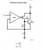
i design this current source( no need to mention its stupid desing). the load change from 1865ohm to 1765ohm (linearly- i hope) and the design can give 10mA +/- 2uA. the simulation work perfect. my questions are
1. is it possible to impliment this desing
2. how can i impliment summing point - please see the attachment
modification are warmly welcome

thank you
 

Attachments

  • SCHEMATIC1 PAGE2.pdf
    37.5 KB · Views: 284
  • perfomance.pdf
    24 KB · Views: 170
I would suggest you google for 'opamp constant current source', as your 'design' isn't one. You monitor the voltage across the emitter resistor, not across the load, as you're setting a voltage, not a current doing that.
 
I would suggest you google for 'opamp constant current source', as your 'design' isn't one. You monitor the voltage across the emitter resistor, not across the load, as you're setting a voltage, not a current doing that.

thank you for reply
for first attemt i used the Howland architectue but no use and little hard to understant theory behind that architecture.
for this desing i just bias transistor so that it gave required current and monitor p.d across load and feed it to differnetial amp and readjust the bias setting of transistor when load change
i use emmiter resister as my load. so is there any wrong with that ???
 
Last edited:
You're monitoring the voltage across the load, so it's constant voltage - not constant current.

Load should be in the collector, and you should monitor the voltage across the emitter resistor, it then monitors the current.
 
oh my bad :eek::eek::eek:
i gave wrong info. in my desing i didn't have any emitter resistor. insted load was put in collector - sorry for mislead you Mr.Nigel:( . i'll correct and reply tommorow - (i don't have pspice on my pc)

any way thank you Mr. Nigel
 
The reference at the (+) input of the TL072 is only 4 millivolts. Since the input offset voltage of the TL072 is up to 5 millivolts, the error is greater than your intended signal.

The 90k resistance from the load to the (-) input of the TL072 consumes more than 2% of the load current. This is 100 times more error than you are permitted.

The 200 parts per million (10mA +/- 2uA) goal is an exercise in error management. Your task is to limit the number of factors which contribute to the error. If four resistors are in the error path, they need to be precise to about 50ppm, which is very expensive. (Assuming no other error; see the op amp; above).

1. is it possible to impliment this desing
No. Voltage sources of 19.003Vdc and 24.37000Vdc will not be found outside the laboratory.
 
Last edited:
hi mneary
thank you for you explanation
yes i'm in sort of laboratory (but not much equipped) ok i have to redesign this, i have couple of op-07 and ne5534ang low offset op amps, this is really headache to me. as nigel suggest i was moniter voltage drop in emmiter and controll the emitter current to stay constant, yes it work but you know Ie= Ic+Ib so to keep Ie constant Ib and Ic have to change. Ic can't keep constant in milivolt range :(
then i try to put a low precise resistor on collector and monitor voltage across it and controll the Ic current. still struggle to make it but have hard luck
 
hi
i change my design. appreciate your further advise
 

Attachments

  • SCHEMATIC1 PAGE1.pdf
    36.2 KB · Views: 176
  • parametric simulation.pdf
    24.6 KB · Views: 152
Last edited:
You need to clarify your requirements. Do you understand what it means to stay within 2µA of 10mA? This is hard, because you aren't building an ordinary reference. This is specified to be extraordinarily accurate.

Your requirements cannot be met with any 5% tolerance zener diode such as the 1N5225. 5% tolerance is 500 microamperes! You should consider a precision voltage reference. Remember your total error needs to be 0.02%

It's good that you attempted to only have one resistor (R1) contributing to errors, but it needs to be carefully specified precision component. Even 1% would contribute 100µA error which is not good enough. As noted by Nigel, R1 is giving you misleading results. The circuit should work without it.

Your TL072 cannot handle an input attached to 30V. Its supply is only 18V! Study "common mode range" for more than I can write here. Short answer is that +Vcc needs to be greater than +Vdd. (-Vcc doesn't need to be -18V; you can attach to 0V)

But tje TL072 isn't good enough. Although its input current is low enough, an offset voltage of 5mV reflects 5µA error into the 1K R2. You're moving in the right direction, though.

The open collector architecture is good at tolerances of maybe 1%, but it's totally unsuitable for your 0.02% tolerance. Maybe a P-channel FET would do the job.

Summary: Precision reference, precision resistor(s), reduce Vdd, increase +Vcc, make (-Vcc)=0, reduce value of R2, and PFET as Q1.
 
I would be remiss if I failed to mention that an N-channel FET, e.g. 2N7000/2N7002, could be used if you invert the op amp inputs.
 
You need to clarify your requirements. Do you understand what it means to stay within 2µA of 10mA? This is hard, because you aren't building an ordinary reference. This is specified to be extraordinarily accurate.

yes i clearly unders stand, i give up that extream accuracy which was my ultimate goal. but it should at least 50µA accuracy
in breaf i'm determining junction temperature of HB led, for that i want some high precise current source.

thank you for reply and i surely attend the issue you arose
 
so you want to drive a HBLED with a known constant current and determine the temperature from the T/Vf curve of the LED(i.e. by measuring the forward voltage), correct?
 
Last edited:
you can drive the transistor with a single-ended op amp current source and provide feedback to the op amp with a current sensing resistor as shown here....
 

Attachments

  • currentsource-sink.jpg
    currentsource-sink.jpg
    35.1 KB · Views: 137
so you want to drive a HBLED with a known constant current and determine the temperature from the T/Vf curve of the LED(i.e. by measuring the forward voltage), correct?

yes, some thing like that
 
can i use Voltage Reference IC like TL1021 instead of zener diode will it be practical
Farnell Export
 
in the circuit i provided, Vin should come from a precision voltage reference. for driving HBLEDs, you only need a 5-10V power supply. for 300mA (assuming a 1W LED) use a 1.2V reference, and R1 will be 4Ω
 
errrrrr....... a search for a TL1021 turns up an AR-15 handguard removal tool, a lawn mower, a class D monoblock amp, and a radio control mechanical linkage. a search of TI's website comes up blank.


go with an LM431, they're common as dirt.
 
hi unclejed613
thank you for reply, my case is little bit different than you mentioned :eek:. i have 7w HB led bulb (7, 1w leds) i don't have any specifications for that single led. i only know the bulb is 7w(as per the manufacture)
so i don't have any T/v graph, so i have to made it my self.
as per your design, R=4Ω and Vref=1.2v the current will be
some thing around 300mA, this is much current than i required. my led bulb already has smps current driver just i want to know what is the junction temperature when it drive with its own current source. for that first i drive with its own current driver for couple of minutes to heat the junction the stop it and supply 10mA like small current to avoid junction heating and measure the voltage drop across leds and determine junction temperature.
 
errrrrr....... a search for a TL1021 turns up an AR-15 handguard removal tool, a lawn mower, a class D monoblock amp, and a radio control mechanical linkage. a search of TI's website comes up blank.


go with an LM431, they're common as dirt.

sorry for bad link
**broken link removed**


**broken link removed**

another problem why do you use darlington like pair in your design? what is the purpose of Q2 2N2219 transistor
 
Last edited:
Status
Not open for further replies.

Latest threads

New Articles From Microcontroller Tips

Back
Top