Continue to Site

Welcome to our site!

Electro Tech is an online community (with over 170,000 members) who enjoy talking about and building electronic circuits, projects and gadgets. To participate you need to register. Registration is free. Click here to register now.

  • Welcome to our site! Electro Tech is an online community (with over 170,000 members) who enjoy talking about and building electronic circuits, projects and gadgets. To participate you need to register. Registration is free. Click here to register now.

How do I get this relay working?

Status
Not open for further replies.

Lithium2142

New Member
Hello!

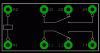
Does anyone know why the relay in the circuit I attached (2 pictures) inst changing?

Facts...
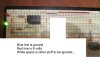
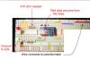
red line = 9.3 ish volts
blue line = ground
The potentiometer works - I tested it and it does vary the voltage...
LED lights are in the correct direction...
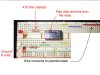
The resistors you see are 470 Ohm resistors.
The relay part is manufactured by Shinmei - RSB-5-S
^^^Specifications are on https://info.tactnet.co.jp/shinmei/e/product/pdf/E_RSB.pdf


No matter what I do the red LED does not turn on, and the Green LED does not turn off. What am I doing wrong?
 

Attachments

  • IMG_0143.JPG
    IMG_0143.JPG
    147.6 KB · Views: 300
  • IMG_0140.JPG
    IMG_0140.JPG
    154.5 KB · Views: 269
How about posting a schematic so we don't have to try to decipher it from your layout.
 
It looks like you are running 9v to both pins of the coil.

You need a GND.

remove the second jumper from 9v to the coil and jump it to GND instead.
 
You might also check the relay contact wiring.

Here is the symbol for the relay.

NC -> 11 - 12, 21 - 22, NO -> 11 - 14, 21 - 24

Boncuk
 

Attachments

  • S30.gif
    S30.gif
    9.3 KB · Views: 369
I was looking for the relay online when my Internet went south. I notice in Boncuk's pinout that one pin shows + for the coil. Does this relay have an internal diode across the coil and if so, is the polarity connected correctly? Also, if the side of the relay with the bar (line) is the coil pins, they both look to be going to 9 volts.

Ron
 
Last edited:
I was looking for the relay online when my Internet went south. I notice in Boncuk's pinout that one pin shows + for the coil. Does this relay have an internal diode across the coil and if so, is the polarity connected correctly?

Ron
good call. That would make a difference with polarity.
 
I did find the pinout and yes, there is an internal diode across the coil. Pin 1 (+) and pin 16 (-). Additionally it does look like the coils pins are both tied to the supply of 9 volts or whatever.

Ron
 
This is what I get for making air circuits. I can't read one of those boards from a photo, even after 3 people have shown it could be done.:(
 
This is what I get for making air circuits. I can't read one of those boards from a photo, even after 3 people have shown it could be done.:(

I can't do it when I am sober. :)

Seriously, I hate doing it and especially when wire colors change.

Ron
 
Well, I hope you get this working. I've been sober for years and I don't expect to improve enough to read that circuit before you get results.
 
I was looking for the relay online when my Internet went south. I notice in Boncuk's pinout that one pin shows + for the coil.

Ron

Hi Ron,

the "+ sign" you see is the zero/zero reference mark which cannot be suppressed in Eagle.

That kind of relay is manufactured by many companies and fits perfectly into a modified DIP-16 socket.

My example is of the "FINDER S30", which might have different pin numbers (according to German standards the common pin is 11, 21, 31 etc, NC pins are 12, 22, 32 and NO pins are 14, 24, 34.

Regards

Hans
 
Hi Hans

Using the link once I had good Internet back the relay does in fact have polarity on the coil. They even offer it with a reverse polarity for the pins. Tonignt was just one of those nights. My Internet speed began to slow, the real slow then a stop. Rebooted the modem and it would not lock on. After a few min it locked on the node and been fine ever since. I hate it when that happens. Anyway as someone else mentioned long before me, on the breadboard it doesn't look right. Looks like power + is running to both sides of the relay coil. I guess when the OP returns we will know.

Ron
 
The coil is shorted out with no ground, show the rest of the board, this forum hates secrets.
I bet the OP already figured that out and that why he hasn't posted again.
 

Attachments

  • Untitled.png
    Untitled.png
    1 MB · Views: 379
Last edited:
And the OP said,

cricket, cricket

I'm thinking about making that my signature line:D

Is that about the same as we use to say in Germany? "April - April"?

Boncuk
 
Cricket, cricket

And the OP said,

cricket, cricket

I'm thinking about making that my signature line:D

-I love that line.

Thanks for your help!

I got it working... And it was because I stupidly had A1 and A2 (Boncuk's diagram) connected to + instead of one connected to ground. It turns out that the pin left of the S in Shinmei connects to ground, and the opposite pin connects to +.
I'll post a schematic if I have any other future problems :)
And I would have replied earlier, except that I was sleeping.

-Lith

Edit: How do I mark the thread as solved?
 
Last edited:
@ Lithium...you just did.

@ Boncuk...I don't know.

The meaning of "cricket, cricket" is that it is so quiet you can hear the insects chirping, a big, empty silence. I see that it does not translate into some languages. I wonder if it translates into Brit, Ozzie, Canuk, Francais, Espanol, Cyrilic based languages, several Asian languages, and Near Eastern languages.
 
The "crickets" line is often used for talking to politicians. You ask them why they are crooked or corrupt, and their answer is " " absolutely nothing. They are so quiet, you can hear the crickets chirping. ;)
 
Status
Not open for further replies.

Latest threads

Back
Top