Continue to Site

Welcome to our site!

Electro Tech is an online community (with over 170,000 members) who enjoy talking about and building electronic circuits, projects and gadgets. To participate you need to register. Registration is free. Click here to register now.

  • Welcome to our site! Electro Tech is an online community (with over 170,000 members) who enjoy talking about and building electronic circuits, projects and gadgets. To participate you need to register. Registration is free. Click here to register now.

how do i control a LH155 driven LCD using an arduino microcontroller?

Status
Not open for further replies.

jpoopdog

Member
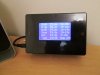
I have a large number of these LCDs **broken link removed**
which i want to use, if i am able, i can get thousands for free if i wanted to.
The driver used is this https://www.andilcd.de/medien/en/download/controller/andilcd_congraf_sheet_en_lh155ba.pdf

From what ive learned so far, the LCD can be driven using using something called SDA and SCL which are serial data of sorts, and that the driver is note quite i2c compliant, whatever that means.

Pretty much i just want to be able to get to the point i could work out the signal i needed to produce a single dot on the screen. At which point i can handle it myself for how to draw text and such, i just need to find out how to get to that stage, where i can calculate or work out a specific signal i could send to get a specific display , ideally using whatever libraries or whatever are used by the stm32 via arduino as i use it for most everything these days. if im limited to something specific though thats fine, porting will be simple enough. I have a rough idea on what i need to do but not the logic protocols or whatever that i need to follow, this is new territory for me, generating specific data in a frequency or binary i think, bitbanging, etc.

hopefully though an LH155BA driver exists somewhere on the internet, though i cant find one.
I appreciate your patience in this.
 
The chip uses I²C to transfer data but you must still setup the chip select and RS lines before the transfer and P/S needs to be low.

I couldn't find an address for the I²C in the datasheet but there are I²C sniffer programs available to find out.

Just write functions to read and write data and commands and just follow the datasheet.

Mike.
 
I couldn't find an address for the I²C in the datasheet but there are I²C sniffer programs available to find out.
Although it appears I2C... It is basically SPI some of the TFT drivers use a similar interface.. SDA is primarily a data input, there seems to be no read via serial.. it is the original "two wire serial"

BTW!! Arduino isn't a microcontroller!!! The Atmega chip in the middle of the Arduino board is..
 
Hi,

Have to ask what would you want to do with thousands of those screens ?

Its a 128x64 pixel, about 55mm wide with a YG blacklight and a FDC type connector and looks like it needs extra component to set up it power supply.

Cannot imagine any hobbyist wanting to buy a display with all those impediments when there are so many better colour ones on the market so cheaply.

Looking at the Arduino screen driver routines I have, there is no sign of that LH155 or anything like it.
Most drivers are actually very similar, it typically just the initialization routine parameters that are slightly different, its not that difficult to modify an existing driver, just needs a bit of patience and a long look at the controllers datasheet.

Not quiet sure what you mean by "stm32 via arduino" ? do you mean you are using the arduino as a slave to drive the display , when you could just use the stm ?
 
i meant i program the stm32 using arduino IDE, any time i bring up the fact i use an stm32 people seem shocked that its even possible to program it with arduino code.

Anyway, yours and my definitions of cheap vary a little, but, this is partly just because i have a useful and large resource at my disposal and the only obstacle is skill, and, from what ive seen so far it seems to be achievable for myself.

Also if we go by physical size, then getting screens of the same dimensions and no less resolution actually would be a tad bit pricey.

I have 3 uses in mind for these

1: casually toss them into anything and everything just because its free
2: building a serial monitor to display serial write commands instead of switching between com ports in arduino IDE on the stm32 ( its my favourite board but programming and reading serial are on seperate COMs), and even anywhere else its just handy to be able to plug a monitor into everything i make and see how its going

3: if youve ever played the game/program synthesia (like a piano version of guitar hero except its actually for learning an instrument), there are issues that arise from the fact the screen and keyboard are so far apart. Basically i want to set up these displays sidebyside to run my own MIDI reading program (run on PC) that scrolls in a similar fashion. Timing isnt really an issue, after a minute or so i know when each key will be hit and when, the purpose of the LCDs is just to help line me up on the exact correct key, so i dont need to look ahead so far. really this is just a step or 2 beyond making the keys light up to indicate which ones i need to press.

Other than that its just a desire to learn.


From what ive found out, the information i send to the SDA will be along the lines of bit strings or something, using RS id define a location then over SDA output something like 0b111000 to set 3 pixels to on/black going horizontally from the position defined.
another option is direct memory access and generating some sort of pixel map in the ram which supposedly can accomplish the task quicker though might require a second board like an STM8 to act as a dedicated driver if i needed to do much else and also run the LCD as fast as it could be driven, not that ill likely need more than 1fps

As for implementing anything, i have no idea. Like, do i just serial write everything to the SDA? i dont need any special libraries for making text i can manage that myself, i just need to get to the point i can make something happen on the LCDs like blinking a single pixel somewhere or something.
 
Hi,

Just assumed you were using on of the little STM boards which typically come with its own programmer on board, so guess yours does not have one or you are burning just the chips.

Any ascii text you outputto a graphic screen first has to be converted to produce the appropriate pixels according to the font and point size you want the image to produce.
Similarly you can upload a bitmap image of a picture etc.

Think if you have a look at the UTFT files this site has it might give you a better idea, though not all have spi options.
**broken link removed**

Also have a look at this old forum post and its zip file which does have a spi interface and the code, though assembler , does seems to show how the datas sent across.
https://www.electro-tech-online.com/threads/glcds-with-pic-18f-assembler.40676/

I've just been using a 128x64 with spi to act as a 6 line display and it works fine, though have not yet tired any graphics, but when helping a friend get his spi display working he pointed out as well as the spi lines he also has a D/C connection ?
Seems thats for hardware control of Commands and Data, so expect you need different driver software for that, expect it speeds things up, but not sure if has to have that control to work or is optional ? just one of such mysteries ! :confused:

TFT screens can be a pain , but equally you can set one up yourself with a lot of time and effort.

hth
 

Attachments

  • IMG_0805 (1).JPG
    IMG_0805 (1).JPG
    97.2 KB · Views: 160
i mentioned this before but currently im more interested in just getting anything to display, im more than capable of writing my own library to display text. When i said serial write i meant sending bytes that say, otherwise, how do i send the data and what data am i sending?
 
As those links might have shown, as does the controllers datasheet page 25, on power up you first have to send out a series of Commands to initialize the display.
Then you send Commands telling it where you want to place the first bit of data , followed by the actual byte of Data.

As the manual shows the spi outputs commands and data on the SDA line, with the SCL and two other control lines.
 
Status
Not open for further replies.

Latest threads

New Articles From Microcontroller Tips

Back
Top