Continue to Site

Welcome to our site!

Electro Tech is an online community (with over 170,000 members) who enjoy talking about and building electronic circuits, projects and gadgets. To participate you need to register. Registration is free. Click here to register now.

  • Welcome to our site! Electro Tech is an online community (with over 170,000 members) who enjoy talking about and building electronic circuits, projects and gadgets. To participate you need to register. Registration is free. Click here to register now.

how do i connect this ULN2308

Status
Not open for further replies.

defcon31

New Member
hello, can someone explain to me how i connect this 24V DC motor on the figure to the ULN component?
thanks in advance,
a newbee
 

Attachments

  • uln2308.JPG
    uln2308.JPG
    8 KB · Views: 2,754
defcon31 said:
hello, can someone explain to me how i connect this 24V DC motor on the figure to the ULN component?
thanks in advance,
a newbee

What sort of power is the motor? - the ULN2308 isn't a very powerful driver, you also can't use it to reverse the motor - only to turn it on and off (and vary the speed by feeding PWM through it).
 
in fact, the motor is only an example.
but what i have to know is where to connect
the "+" from the motor and "-" to the ULN...

do i have to connect the "-" to the ground (on pin 9)
and the outputs of the ULN to the "+" ???

or does the ULN only works like the examples on:
**broken link removed**

because i'm a bit confused because of this example...

thanks in advance.
 
defcon31 said:
in fact, the motor is only an example.
but what i have to know is where to connect
the "+" from the motor and "-" to the ULN...

do i have to connect the "-" to the ground (on pin 9)
and the outputs of the ULN to the "+" ???

You connect the motor to the output pin of the ULN2803, and the other side of the motor to your positive supply (which side of the motor you connect where depends which way you want it to turn.) The extra connection on the ULN, labelled Vcc, should also go to the positive supply - this is the connection to back-emf protection diodes included in the chip.

So, to put it simply, the ULN2803 switches the negative side of the supply, so the load goes from the output pin to positive of the supply.
 
thanks, this was just what I thought...
as i understand it good, the ULN can only let the 24V "sink"?
is my figure right?

but what about with the connection with this optocoupler 4N33 then?
how do I have to connect this? (see below in figure)

thanks in advance
 

Attachments

  • uln2308_4N33.JPG
    uln2308_4N33.JPG
    18.1 KB · Views: 1,818
defcon31 said:
thanks, this was just what I thought...
as i understand it good, the ULN can only let the 24V "sink"?
is my figure right?

but what about with the connection with this optocoupler 4N33 then?
how do I have to connect this? (see below in figure)

thanks in advance

Yes, it can only sink current.

For the 4N33 first connect a series resistor in one of the leads (or you will blow the LED), it doesn't matter which lead, work the value out from ohms law. Connect the anode of the LED to the positive supply (top of your 4N33 diagram), and the cathode to the ULN output pin - bear in mind, one of these must have the resistor in series with the lead, so you connect to the resistor and not the actual pin.

Depending what it's been fed from you may not need a driver to feed the 4N33, a PIC (for instance) will happily feed the LED direct.
 
damn damn damn,

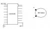
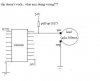
if i understand it well then i'm in big big trouble since the optocoupler is part of an already printed PCB as shown in the figure below. the ground of the 5V is already connected to the ground of the input led of the 4N33 as you also see on the figure.

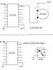
the story you told is just what i was affraid of... when i connect the pin2 of 4N33 to an output of the ULN, the ground of the PCB (where the 4N33 is part of) isn't a ground anymore, so it will disturb also the 5V output of the 4N33... am i right with my suspicions?

i only can test it out friday, but if this is true it is a realy disaster ! :?

is there another solution? can you help me please?
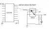
the PCB of the ULN isn't ordered yet, so maybe i can fix something on that side to let the PCB of the 4N33 work correctly this way???
any suggestions???
(since there are already 250 PCB's of that 4N33 delivered (a lot of money), i hope you understand how big my problem is).
 

Attachments

  • uln2308_4N33_2.JPG
    uln2308_4N33_2.JPG
    14.7 KB · Views: 1,788
i hope i can fix the problem right above here with something like this (figure below), by a pull-up resistor or something?

will this work?
if not, please why not?
and do you have any other suggestions ? (because i'm in really trouble now)
 

Attachments

  • uln2308_4N33_3.JPG
    uln2308_4N33_3.JPG
    18.2 KB · Views: 1,769
Yes, a pullup resistor will work fine, bear in mind it will invert the action of the ULN - when it's turned on the LED will be off, and when it's turned off the LED will be on.
 
unfortunately this doesn 't to work.

but when i replace the load of 300mA by a resistor of 10K + a Led, i works fine..
but with the load i drawed in the figure, it doesn't work..

however, the ULN2803 can provide 500mA on each output...

i don't understand it...

what am i doing wrong?
how can i fix it? or is there another possibility for connecting the scheme?

please help me because it 's very important !!!

thanks in advance
 

Attachments

  • uln2308_4N33_4.JPG
    uln2308_4N33_4.JPG
    13.9 KB · Views: 1,630
No - you can't feed a motor through a 1K resistor - it will only work for a low current device like an LED.

From what you said previously you only have 4N33 PCB's so far - it will be OK with those, if you are going to use a motor PCB as well, make sure you design it correctly.
 
If you are looking for a "Sourcing" type driver, use UDN2981. It can source 500mA current and has similar pin-out as ULN2803 except for Vs and GND.
Datasheet: **broken link removed**
 
thanks, the UDN2891 should bring the solution.
have some question about that component:
in the datasheets they talk about maximum rating of "-500mA"
- is it 500mA for each output?
- why do they talk about "-" 500mA? (dont understand why negative).
thanks
 
The datasheet does not clearly mention whether it is the total current or current of individual outputs. But I guess it should be 500mA for each output.
-500 indicates that the current is flowing out of the chip. i.e Current Sourcing.
 
Looking at the graph in the data sheet, it appears the 18 pin DIP 2981 package can desippate alittle over 2 watts max @ 25C.
 
2Watts at 25°C ??????
so when i connect a load that asks 300mA at 24V the chip will be damaged? (=P=U*I=24*0,300=7,2 ?)
is this correct?
 
defcon31 said:
2Watts at 25°C ??????
so when i connect a load that asks 300mA at 24V the chip will be damaged? (=P=U*I=24*0,300=7,2 ?)
is this correct?

No it's not - when the chip is turned off, you have 24V but no current, so 24V*0A=0W. When it's turned on you have very little voltage (you would need to measure it to find out exactly how much) as the voltage is all across the load (which is where you want it), and the current is 300mA. So assuming the voltage dropped across the chip is 1V (I would expect less), 1V*0.3A=300mW.
 
of course that 's correct, sorry for the stupid question.
i was getting already sick that this chip also won't work.
thank in advance
 
You can expect about 600mw (max) dissipation per output which is sourcing 300ma. This means that, with the 18 pin DIP at 25C ambient, you can have as many as 3 outputs on at a time. I wouldn't advise touching the package under these conditions. :)
 
Nigel,
on which pins do you measure the voltage across the chip when the load is connected ? the voltage between Vcc and GND, or the voltage between the output pin and the ground ?
thanks
 
Status
Not open for further replies.

Latest threads

New Articles From Microcontroller Tips

Back
Top