defcon31 said:Nigel,
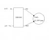
on which pins do you measure the voltage across the chip when the load is connected ? the voltage between Vcc and GND, or the voltage between the output pin and the ground ?
thanks
The output pin and ground!. Vcc and ground would just measure the supply rail.