confounded
New Member
Hi, im not sure how to connect a 2.5mm power supply socket to the pcb i have.
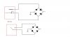
I'ts a project from a magazine. The schematic shows 3 terminals on the socket, as i've shown on the top half of my sketch.
The pcb has 2 of the terminals connected together, as i've shown on the bottom half of my sketch.
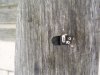
I've attached pics of the socket.
I have used my multimeter to measure resistance between points, the results are:
with no power lead connected:
A-B = open circuit
A-C = open circuit
B-C = short circuit
with power lead connected
A-B = open circuit
A-C = short circuit
B-C = open circuit
Which points on the bottom half of my sketch are A, B and C?
I'ts a project from a magazine. The schematic shows 3 terminals on the socket, as i've shown on the top half of my sketch.
The pcb has 2 of the terminals connected together, as i've shown on the bottom half of my sketch.
I've attached pics of the socket.
I have used my multimeter to measure resistance between points, the results are:
with no power lead connected:
A-B = open circuit
A-C = open circuit
B-C = short circuit
with power lead connected
A-B = open circuit
A-C = short circuit
B-C = open circuit
Which points on the bottom half of my sketch are A, B and C?

")
