Continue to Site

Welcome to our site!

Electro Tech is an online community (with over 170,000 members) who enjoy talking about and building electronic circuits, projects and gadgets. To participate you need to register. Registration is free. Click here to register now.

  • Welcome to our site! Electro Tech is an online community (with over 170,000 members) who enjoy talking about and building electronic circuits, projects and gadgets. To participate you need to register. Registration is free. Click here to register now.

How can I use opamp or any component for my problem ?

Status
Not open for further replies.

karekok

New Member
Dear Friends;

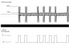
I m looking for true component for my problem. In attached file. There is ossiloscope output. and What is my need ?

Could you control and how can i achieve it?

I tried opamp. But I didnt adjust Input offset voltage. Which component is suitable for me?

thanks a lot

regards...
fatih

fatihozturk76@gmail.com
 

Attachments

  • problem2.JPG
    problem2.JPG
    30.6 KB · Views: 207
Last edited:
mike11298 said:
It hasnt changed much.. have a look on google

there are 2 methodes.
1. Opamp Application. But Opamp is sensing 20mV. So Always Opamp is giving High Output.
2. Transistor Application. Transistor is not sensing 150mV It need 1V.

If I adjust Opamp Input Offset Voltage. Maybe I can do it. But How ?
 
karekok said:
there are 2 methodes.
1. Opamp Application. But Opamp is sensing 20mV. So Always Opamp is giving High Output.
2. Transistor Application. Transistor is not sensing 150mV It need 1V.

If I adjust Opamp Input Offset Voltage. Maybe I can do it. But How ?

hi,
You can use a comparator to detect the difference in the voltage levels.

The comparator can be configured to give a TTL output level whenever the signal is greater than say, 50mVolt.

A fast comparator will give TTL pulses each time it senses greater than 50mV,
so you could use a simple resistor/capacitor filter to remove the comparator output 'spikes' or allow the high output edges to re-trigger a monstable to give a clearer pulse.

Do you know how to do that?
 
ericgibbs said:
hi,
You can use a comparator to detect the difference in the voltage levels.

The comparator can be configured to give a TTL output level whenever the signal is greater than say, 50mVolt.

A fast comparator will give TTL pulses each time it senses greater than 50mV,
so you could use a simple resistor/capacitor filter to remove the comparator output 'spikes' or allow the high output edges to re-trigger a monstable to give a clearer pulse.

Do you know how to do that?

Dear Eric;

Thanks for useful informations. How can i use comparators. I dont know.

Could you prepare simple circuit for me?. I can try something with your circuits or Which comparators is suitable for me ?

many thanks for your time.
 
karekok said:
Dear Eric;

Thanks for useful informations. How can i use comparators. I dont know.

Could you prepare simple circuit for me?. I can try something with your circuits or Which comparators is suitable for me ?

many thanks for your time.

hi,
Get the datasheets for the LM392 and LM393 from www.datasheetarchive.com

Study the data sheets and try to follow the application notes, post a simple drawing on how you think they would be connected
and we will help you thru it.
 
You might also want to add a low pass filter on to the input of the comparator to get rid of those nasty high frequency harmonics which might cause it to switch on and off very rapidly.
 
Hero999 said:
You might also want to add a low pass filter on to the input of the comparator to get rid of those nasty high frequency harmonics which might cause it to switch on and off very rapidly.

dear friends ;

thanks a lot for your time. . I m just trying L272M Opamp. Input Offset Voltage is 15mV. May It will work. I can try Low pass filter with opamp.

regards...
 
karekok said:
dear friends ;

thanks a lot for your time. . I m just trying L272M Opamp. Input Offset Voltage is 15mV. May It will work. I can try Low pass filter with opamp.

regards...

hi,
If you use the L272 as an amplifier it will not give give you what you want, it will just amplify everything!

If you must use the L272, configure it as a Comparator.
 
But as the signal is so small he really needs an amplifier before the comparator to ensure reliable operation.

He also wants a precision rectifier to remove the negitive before the low pass filter.

This isn't as simple as everyone first thought.
 
It would really help to know what the time scale is, and the carrier frequency. It looks like simple AM digital data.
 
Hero999 said:
But as the signal is so small he really needs an amplifier before the comparator to ensure reliable operation.

He also wants a precision rectifier to remove the negitive before the low pass filter.

This isn't as simple as everyone first thought.

hi,
A Comparator will easily detect the difference in levels between 20mV and 150mV, it dosn't need an amplifier. Just set the Vref at about 80mV.

It also dosn't need a rectifier, just a simple RC filter on the comparator output
 
ericgibbs said:
hi,
A Comparator will easily detect the difference in levels between 20mV and 150mV, it dosn't need an amplifier. Just set the Vref at about 80mV.

It also dosn't need a rectifier, just a simple RC filter on the comparator output

please give me circuit schematic with L272M as a comparator between 20mV -150mV . So I tried some comparator circuit. But No answer.
 
hi,

Tell me what the 'p1' , 'p2' time periods are, also the frequency of the spikes, refer the gif drawing.

Then I will try to help.
 
Last edited:
Status
Not open for further replies.

New Articles From Microcontroller Tips

Back
Top