Continue to Site

Welcome to our site!

Electro Tech is an online community (with over 170,000 members) who enjoy talking about and building electronic circuits, projects and gadgets. To participate you need to register. Registration is free. Click here to register now.

  • Welcome to our site! Electro Tech is an online community (with over 170,000 members) who enjoy talking about and building electronic circuits, projects and gadgets. To participate you need to register. Registration is free. Click here to register now.

How can I modify this to use higher voltage & current display?

Status
Not open for further replies.

wubs

New Member
Hello.

First, let me say this circuit works as is -- it is a 99 minute timer.

Second: I am NOT a student nor a manufacturer. I am a hobbiest who is struggling with electronics.

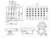
Because I have impaired vision, I want to use larger, 2.3inch 7 segment LEDs than the half-inch LEDs that were used in the original circuit shown here. :(

My new 7 segment LEDs are also common cathode, but they require 7.5 @ 10mA.

My idea is to use either a 9V or 12V supply and use an LM7805 for the PIC and an LM317 adjusted to put out 7.5V (I already know how to do that, so I only need to see how to drive the LEDs from that 7.5V so that I don't blow up the PIC.

Thank in advance for any advice you can give me! :D
 

Attachments

  • countdown.gif
    countdown.gif
    22.9 KB · Views: 299
Powering the Vdd pin on the 4511 with 7.5V instead of 5V is the place to start. However, this might create a couple of problems which may/or not prevent it from working...

Raising the supply voltage on the 4511 while still operating the PIC on 5V means that you have reduced the margin on having the 4511 recognize a logic one (Vih) on its inputs when the output from the PIC only pulls to a Voh of 5V.

Hopefully, the voltage drop through two LEDs in series in each segement will prevent the PNP transistor from turning on while the anode of the LEDs is at 7.5V. The emitter of the transistor (Cathode of the LED segement) cannot be higher than one Vbe (~0.6V) above 5V, other wise the segment will be partially on while it is supposed to be off.

Try it and see if it works. Make the 7.5V adjustable. It may work at 7V, even if it doesn't work at 7.5V. You cannot raise the Vdd on the PIC above 5.5V.
 
Last edited:
You can replace the PNP transistors with four sections of a 7407 non-inverting open-collector buffer and then raise the Vdd of the 4511 as high as it will tolerate. (Keeping the Vdd of the PIC and 7407 at 5V of course.)
 
It's going to be ugly and bodgy unless you totally redesign it. You will need more than a 7.5V supply due to the Vbe drop of the PNPs, voltage drop through the 4511, and a required Vdrop for the LED current limiting resistors.
 
Powering the Vdd pin on the 4511 with 7.5V instead of 5V is the place to start. However, this might create a couple of problems which may/or not prevent it from working...

Yup, you're right about that!

And, of course, just plunking in these larger LEDs in place of the originals resulted in them being very dim.

Thanks for the ideas you gave, however. I learn this way, since I have no formal education in electronics, it is only through the wisdom of others that I can glean bits and pieces about how it all works. ;)
 
You can replace the PNP transistors with four sections of a 7407 non-inverting open-collector buffer and then raise the Vdd of the 4511 as high as it will tolerate. (Keeping the Vdd of the PIC and 7407 at 5V of course.)

This is one of those bits of wisdom that I am gathering; I have no idea what it means, but I will try to figure it out! :confused:
 
It's going to be ugly and bodgy

Much like me! :D

unless you totally redesign it.

Well, a designer is definitely something I am not. I am scouring the internet for circuits that use a large common cathode 7 segment display. I have found some that use common anode, but none so far that use common cathode type.

If there is a way to modify the circuits to use common cathode, I haven't come across an explanation yet. :(
 
You can replace the PNP transistors with four sections of a 7407 non-inverting open-collector buffer
He could use 74LS07s to also level translate the BCD data for the 4511 as well as for the digit drivers. It is ugly, but could look like this:
 

Attachments

  • countdown.gif
    countdown.gif
    31.1 KB · Views: 217
What's the part number and color of those 2.3" displays?

I don't have a part number (at least none that I can see anywhere on the LED).

However, here are the specs from the eBay listing along with an image of the LED's characteristics:

  • Type: Common Cathode
  • Size: 2.3'' (L 69.70mm x W 47.80mm x D 12.00mm)
  • Forward Voltage: 7.5V
  • Forward Current: 5-10mA
 

Attachments

  • 231.jpg
    231.jpg
    18.8 KB · Views: 181
It is ugly, but could look like this:

Thanks for the circuit, kchriste! I'll give it a go when I have some time this coming week.

I'm still looking forward to see what idea/suggestion blueroomelectronics comes up with, though.

This is a great learning experience for me. :)
 
Status
Not open for further replies.

Latest threads

New Articles From Microcontroller Tips

Back
Top