Continue to Site

Welcome to our site!

Electro Tech is an online community (with over 170,000 members) who enjoy talking about and building electronic circuits, projects and gadgets. To participate you need to register. Registration is free. Click here to register now.

  • Welcome to our site! Electro Tech is an online community (with over 170,000 members) who enjoy talking about and building electronic circuits, projects and gadgets. To participate you need to register. Registration is free. Click here to register now.

How can i display respiration waves on osciloscope?

Status
Not open for further replies.

surrounder

New Member
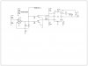
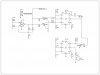
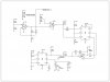
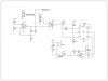
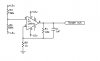
Hello everybody.I need to design a circuit which is thermistor based.I should take the respiration airflow changes by a thermistor then i should display this signal with the aid of osciloscope.How can i make this kind of a circuit design? Thanks in advance.
 
This is interesting, is there anything else you can use besides a thermistor? Thermistors are generally slow to respond to temperature changes.

I have attached a simple circuit that you can use for your circuit. R4 is the thermistor for the ambient temp, and R3 is the respiration sensor. I would try to use a better op-amp than the 741, I only included it because it was quick and easy to find in the parts library.
 

Attachments

  • scope, slope.JPG
    scope, slope.JPG
    23.7 KB · Views: 145
You need a "hot wire anemometer" circuit. There are several on this page -
http://www.fonema.se/anemom/anemom.html

Around the middle of the page you will see one that uses a filament from a broken lamp. I have built these in the past, and they have the fastest response of any of them because of the low thermal mass of the filament. You need to keep the thermal mass of the sensor to a bare minimum for a fast response time, and for that not much beats a tiny piece of nichrome hanging in the breeze.
 
Last edited:
This is interesting, is there anything else you can use besides a thermistor? Thermistors are generally slow to respond to temperature changes.

I have attached a simple circuit that you can use for your circuit. R4 is the thermistor for the ambient temp, and R3 is the respiration sensor. I would try to use a better op-amp than the 741, I only included it because it was quick and easy to find in the parts library.

Thank u so much.But i couldn't understand the difference between of the thermistor(r4) and respiration sensor (r3).I should use thermistor as a respiration sensor for this project. Thermistor will be exposed to subjects respiration air-flow.I'll talk to my project menager i think so thermistor is not sensitive enough for this process.Yours sincerely.
 
Thermistors are used for respiration monitoring in medical equipment. Very small thermistors have very good response time. I would recommend 4 thermistors in a Wheatstone bridge configuration, feeding a differential instrumentation OP amp. Two in the air path and two in still ambient air. This will double the output, plus compensate for variations in ambient air temp.

Ken
 
Thank u so much.But i couldn't understand the difference between of the thermistor(r4) and respiration sensor (r3).I should use thermistor as a respiration sensor for this project. Thermistor will be exposed to subjects respiration air-flow.I'll talk to my project menager i think so thermistor is not sensitive enough for this process.Yours sincerely.

The difference between R3 and R4 is baiscaly their function. R3 is the respiration sensor while R4 is the ambient sensor. There needs to be an ambient sensor because as the temperature in the room changes, both thermistors respond to the change in temperature. When a thermistor gets hotter, it's resistance goes down because they have a negative temperature coefficient. If R4 was a fixed value, then the change in temperature from the room would cause a false reading. This way R4 can compensate and your get a more accurate reading.

KMoffett is right, using 4 thermistors in a wheatstone bridge will give higher accuracy.
 
İt's working time!

Thanks for all of your advices:) I hope that i can figure electronic problems out too.İf i have any problems on process i want to take your advices again.
 
Development of project

Hi everyone i've complated my project group things and i've explained about process of the circuit.So we decided to develop our project with a loud buzzer and LED.İs it posible that connecting a out buzzer and LED which works with frequency changes? For example if respiration stops a buzzer will be activated and if respiration happens a LED will be activated.

Sincerely..
 
I would suggest a monostable multivibrator triggered by the respiration wave and driving the LED. The output of this would also drive a "missing pulse detector" driving a buzzer.

Ken
 
out of curiosity how accurate would the light filliament be for temp detection? sorry i know its not relevant for this OP but i like the idea of a light filliamnet for a temp sensor
 
What kind of application are you envisioning where a bare filament would be better than existing calibrated thermistors or thermocouples?

Ken
 
Last edited:
none i just wondered how good a quick fix solution something like that would be if the need ever arose. i have a naturaly curiosity for tempreture sensor's, it did also cross my mind that one with a wrap round a transistor on a H bridge would make a very cheap sensor for next to nothing. i dont actualy have anything serious in mind for it. 3-4c accuracy tho would make my mind focus on finding a use for it :D
 
A microcontroller would be best for this situation because it can be programed to modify it's parameters based on patterns it recognises. But this is very time consuming and not an easy thing to do. Instead, I would recomend using a 555 timer configured as a missing pulse detector.

Here are two circuits that can be used as missing pulse detectors. The first one will reset itself if activity resumes, while the second will latch itself and must be reset in order to resume. You can have the output driving a second 555 that is acting as a tone generator. If you hold the reset pin on a 555 low (pin 4) then it's output will never change states.

I have attached a few of the schematics that show how you would connect them to your existing circuit.

The first and second can both be reset just by activity on sensors. The third and fourth will latch and will not resume until someone presses the reset button. The first and fourth are for if you are using an off the shelf buzzer like the kind you get at radio shack or such (these little buzzers can deliver an increadle amount of sound at 12V and can easily be heard 50 feet away). The second and third are for if you want to build your own buzzer. If you chose one of these two circuits, the two 555 timers can be replaced with a single 556 timer (just two 555s in one package). I personaly would choose circuit one or four simply because of the power of the buzzers and the fact that they are ready made. The one that I like the best can go up to 36V and you could probably hear it a half a mile away. Here is a link to the one I own: https://www.radioshack.com/product/index.jsp?productId=2102819
 

Attachments

  • Missin1.gif
    Missin1.gif
    10.2 KB · Views: 116
  • LM555MissingPulse3.GIF
    LM555MissingPulse3.GIF
    8.9 KB · Views: 135
  • scope slope alarm.JPG
    scope slope alarm.JPG
    117.5 KB · Views: 121
  • scope slope alarm2 buzzer.JPG
    scope slope alarm2 buzzer.JPG
    140.5 KB · Views: 120
  • scope slope alarm3 latch.JPG
    scope slope alarm3 latch.JPG
    154.9 KB · Views: 128
  • scope slope alarm4 latch buzzer.JPG
    scope slope alarm4 latch buzzer.JPG
    137.2 KB · Views: 120
Thank u so much.I'll try to entegrate this parts to my circuit i hope i could do that.By the way circuit 4 & 5 which Dragon Tamer has shared; are they the circuits which have entegrated to respiration circle?
 
All of the schematics that I made have the respiration measurement worked in. They are labeled scope out and scope ground. The scopes ground must be connected to a 1/2 voltage divider so that the signal will transition from positive to negative on the scope readout. This is necessary because the -12V supply needed to be removed from the circuit in order to interface with the 555 timers. (it could actually have been left in but the circuit would have been more complicated than it needed to be)
 
The schematic program that I use is Express PCB, it can't simulate but it does make the schematics. I have to use a calculator and the known equations for each part to figure out how it will work. If you are trying to use multisim to verify these circuits, then you should know that multisim tends to slow its simulations speed down a lot. It's not a real time simulation so you must modify your schematic to compensate. The 555s are set to trigger if there is no activity for roughly 3.5 seconds. Try cutting the value of the resistors and capacitors of the 555 circuit by a factor of 10. In my experience just because something works in a simulator, doesn't mean that it will work in real life and vise versa. You would be better off building this circuit on a bread board for testing.
 
Thank u so much cause multisim drives me crazy:) I'm going to try all of these applications at labs.
 
Last edited:
Hello again!

Hi everbody. I've tried some of this projections.But my adviser said that it's gonna be better if you create this project with 'wheatstone bridge'. Can you help me about this?
 
Status
Not open for further replies.

New Articles From Microcontroller Tips

Back
Top