Continue to Site

Welcome to our site!

Electro Tech is an online community (with over 170,000 members) who enjoy talking about and building electronic circuits, projects and gadgets. To participate you need to register. Registration is free. Click here to register now.

  • Welcome to our site! Electro Tech is an online community (with over 170,000 members) who enjoy talking about and building electronic circuits, projects and gadgets. To participate you need to register. Registration is free. Click here to register now.

How can I design a simple DC-DC buck step down converter with feedback

Status
Not open for further replies.

Fluffyboii

Active Member
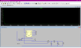
Hi, I have a project which is creating a step down converter that takes 12V and gives 5 volts. It is required to handle 10 Amps which is I think a bit overkill. Anyway since they don't teach us anything in Electronic classes other than stupid imaginary sinusoids most of my teammates doesn't know how to make a circuit. So I tried to create a simple oscillator with everyone's favourite 555 IC and gave the square wave output to the npn transistor. I need to implement some sort of feed-back to this circuit so voltage doesn't drop under heavier loads. I think I need a comparator to detect when voltage goes below 5V and increase the Duty cycle or frequency but since it is fixed by the resistors R1, R2 and the capacitor I don't know how I can change those. I don't want to use any special buck converter IC's for this circuit and keep it easy enough to explain to someone who doesn't know much about this sort of stuff. What can be done can someone explain.
 

Attachments

  • 555.png
    555.png
    39.5 KB · Views: 290
One of the simplest switchers is Hysteretic -

iu


Above simple example. Switch would be MOSFET typically.

https://corescholar.libraries.wright.edu/cgi/viewcontent.cgi?article=2522&context=etd_all Ignore all the heavy duty analysis....

Modules -


Regards, Dana.
 
Last edited:
Here is a data sheet for a small simple buck switcher from TI. buck It is only good for 1A.
I see you want 10A.
Here is the big brother 10A part. 10A. Both papers are good reading with examples.

A "555" is not designed to do PWM. I know the internet is full of stories how the 555 did ...(fill in the blank) but use a real PWM ic and do the job right.
Unfortunately I asked my instructor and he said using a specific buck converter IC is forbidden in this project but using one to create the clock is ok it seems. Is there a more trivial way to do the thing this IC does with more separate components.
 
Unfortunately I asked my instructor and he said using a specific buck converter IC is forbidden in this project but using one to create the clock is ok it seems. Is there a more trivial way to do the thing this IC does with more separate components.
Is solution with more components more trivial? Use IR2153 its basically 555 ic with gate driver. It has no feedback
 
Is solution with more components more trivial? Use IR2153 its basically 555 ic with gate driver. It has no feedback
I mean he wants us to use different ICs, op-amps, more distinct components instead of one IC doing all the work. I need the feedback though.
 
Last edited:
OK, Use a 555 for a clock, opamp for an error amplifier (I would use a TL431 because it is a amp and a voltage reference in one) You will need a voltage comparitor. Most comparitors have OC output which will trick you when it does not work.
This is a learning project.
Internal to a UC3842.
1638193071017.png

Here is an example of a simple Current Mode PWM you can do this in voltage mode which is probably more like what the teacher wants.
1638193323716.png
 
Below is the LTspice simulation of a simple hysteretic converter:
It uses an LM339/393 comparator, and six CD4050 buffers (one package) to act as a driver for the large gate capacitance of the P-MOSFET.
(A MOSFET gate driver IC can be used in place of the CD4050).
A TL431 programmable 2.5V reference is used to set the output voltage at 5V.
C3 provides a slow (soft) start to minimize any output voltage overshoot during startup (otherwise the output would go to about 10V).

It has about 70mVpp ripple with a 10A load, which should be acceptable for most digital circuit requirements.
Note that the inductor must be able to handle at least 10A without saturating.

1638221789750.png
 
Last edited:
Below is the LTspice simulation of a simple hysteretic converter:
I was thinking bout your hysteretic converter, (and another one) but then there is not really a "oscillator". In your version there is not a error amp. I was thinking of one with a osc and error amp but still they are a little unusual and may not have the building blocks for school work.

I think the goal is to build something from nothing and understand each block. I even hate to bring up the idea that a TL431 can be both the reference and and error amp in one.
 
there is not really a "oscillator"
Simple hysteretic converters don't have an "oscillator" (see post #2).
Their switching frequency is determined by any hysteresis in the switching voltage and the output LC time-constant.
It turns the switch on when the output ripple voltage drops below the reference voltage, and turns the switch off when it goes above the reference voltage.
(See below, showing the MOSFET control voltage (red trace, low is ON) versus the differential voltage at the comparator input.)

1638241478528.png

In your version there is not a error amp
Hysteretic converters don't have (or need) an "error amp" as such, they use a comparator in a "bang-bang" configuration.
They have the advantage of being inherently stable and not requiring any frequency compensation of the feedback loop.

I think the goal is to build something from nothing and understand each block.
That may be so, but that was not stated or implied in the original post.
 
but that was not stated or implied in the original post.
Read between the line. (insert happy face here) lol People never ask the question they should or give enough information.

(apples & oranges) What you have I call a Voltage Mode Hysteretic. I have used them in 14.5V to 5V buck supplies.

The first hysteretic converter I did; I call a Current Mode Hysteretic. I used a UC3842 like part that watches the current in the inductor. example: current turns on when the inductor current drops to 1A and turns off at 1.5A. A error amplifier looks at the voltage. The output of the error amp causes the 1A/1.5A levels to more up or down to keep the voltage constant.

Either way I like hysteretic. I like current mode because it responds to short and saturation very fast. I also like constant off time which does a good job of mimicking a hysteretic.
Hi, I looked up both of the DC-DC converter topologies and Hysteretic one seem to be easier to understand from a total electronic noob standpoint. I don't know what is an error amp, PWM latch or the gate that is used in the current mode circuit sample you put. Even though I can understand the concept I don't think I will be able to explain it to my teammates. From my understanding our supervisor doesn't really care as long as we make something functional but I would like to build something semi decent so I can get to learn something. BTW do you know why are we using 2.5V instead of 5V as reference. And how do you use tl431 as an amplifier of some sort. Doesn't it act like a programmable diode, I couldn't find a clear answer. Sorry to bother you all with me inexperience.
 
Below is the LTspice simulation of a simple hysteretic converter:
It uses an LM339/393 comparator, and six CD4050 buffers (one package) to act as a driver for the large gate capacitance of the P-MOSFET.
(A MOSFET gate driver IC can be used in place of the CD4050).
A TL431 programmable 2.5V reference is used to set the output voltage at 5V.
C3 provides a slow (soft) start to minimize any output voltage overshoot during startup (otherwise the output would go to about 10V).

It has about 70mVpp ripple with a 10A load, which should be acceptable for most digital circuit requirements.
Note that the inductor must be able to handle at least 10A without saturating.

View attachment 134678
Can I use IRFP260 mosfet for this. I have appropriate mosfet driver for it from a failed tesla coil project, if I am not wrong it should be capable of switching very fast and has high power ratings. And soldering it would be easier because of its package.
 
Hi, I looked up both of the DC-DC converter topologies and Hysteretic one seem to be easier to understand from a total electronic noob standpoint. I don't know what is an error amp, PWM latch or the gate that is used in the current mode circuit sample you put. Even though I can understand the concept I don't think I will be able to explain it to my teammates. From my understanding our supervisor doesn't really care as long as we make something functional but I would like to build something semi decent so I can get to learn something. BTW do you know why are we using 2.5V instead of 5V as reference. And how do you use tl431 as an amplifier of some sort. Doesn't it act like a programmable diode, I couldn't find a clear answer. Sorry to bother you all with me inexperience.
Yes, the tl431 is a programmable voltage shunt reference, which you can think of as being a programmable zener diode. 2.5 Volts is it's internal reference value.

In crutschow's circuit in post #8, it provides a 5 Volt reference due to the two equal value resistors feeding it's reference pin.
 
I don't know what is an error amp, PWM latch or the gate
There are many different kings of PWM power supplies.
Crutshow's power supply is very simple. (there is not really an error amp) If the voltage is a little low turn on the MOSFET. If the voltage is too high turn off the MOSFET. On of the problems there is this ripple on the output of the supply.

It is typical to have a error amplifier. This amplifier looks at a reference voltage. (2.5V or 5V) and compares the output to the reference voltage. The amplifier has a very large gain so it can see 0.001V error.

Here is a block diagram of a typical PWM ic.
There is a reference output.
The error amplifier looks at Reference and output voltage.
The oscillator makes a "saw tooth" wave form shown in red.
The output of the error amp is a voltage shown in green.
The Voltage Comparator looks at the red and green voltages.
The MOSFET (not shown) is turned on when the red saw tooth starts up and turn off the MOSFET when the saw tooth crosses the green line.
The error amp voltage moves up or down to make the duty cycle bigger or smaller.
1638414135425.png

 
Last edited:
Can I use IRFP260 mosfet for this
Nope.
That's an N-Channel MOSFET.
My circuit needs a P-Channel MOSFET.
They are not interchangeable.
 
Crutshow's power supply there is not a power supply.
What?
there is this ripple on the output of the supply.
All switching power supplies have ripple.
The hysteretic converter may have a little more ripple, but if that doesn't have a detrimental effect on circuit operation, then it's not a problem.
 
Typed wrong. I was wanting to say there is not a real error amplifier.
True, there is not an analog error amplifier (since it doesn't need one).
But I will argue that the comparator is a error amplifier since it senses the voltage difference between the reference voltage and the output voltage.
 
But I will argue that the comparator is a error amplifier since it senses the voltage difference between the reference voltage and the output voltage.
Agree. You build a very good and simple BUCK supply.
Sir, you have satisficed the goal of building a PWM-buck. I worry that the teacher does not really want a Buck PWM but wants to teach as much as he/she can in the limited time.
If you gave an assignment to design a PWM with an error amp, comparator, and on, for the purpose to learn each block, then we need blocks. I would teach response time, phase shift, stability, etc. of the amplifier.
 
Status
Not open for further replies.

Latest threads

New Articles From Microcontroller Tips

Back
Top