Continue to Site

Welcome to our site!

Electro Tech is an online community (with over 170,000 members) who enjoy talking about and building electronic circuits, projects and gadgets. To participate you need to register. Registration is free. Click here to register now.

  • Welcome to our site! Electro Tech is an online community (with over 170,000 members) who enjoy talking about and building electronic circuits, projects and gadgets. To participate you need to register. Registration is free. Click here to register now.

Homemade CDI ignition

Status
Not open for further replies.
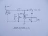
300/440/550 650 wiring diagram has the diagrams for your ignition...Not sure if you have the 3 wire or the 4 wire, but surly we can find a way to "trigger" an aftermarket coil into firing...if any factory coils are able to do just this. I bet you will be better off to take one of your old coils and rebuild it with some heavy duty enamel wire and then put it all in epoxy again. If you put it back with the same amount of "windings" then at least you would have rebuilt the coil for cost of wire. You may be able to add an extra winding or take one away to make the coil output more voltage.

I guess you could use hall effect sensors that are 180 degrees apart and just go to a complete digital system that just sends a trigger to the charged coil to spark?
 
My comment in regards to "bad advice" was in regards to no one has tried to isolate what has actually faild here and has offered advice on various replacement parts without actually knowing what the real problem is.

To me to test the various components and check what is working or not is the best approach, then we can all offer advice on how to solve the problem.

Pete.
 
I have repaired & reverse engineered various electronic equipment which was set in ressin. It was done by carefully chiping the resin away using a small wood chisel. Also a reasonable digital camera using Macro seting goes a long way in recording progress & a record. I also have repaired electronic CDI systems & it is usualy the SCR switching that fails. Have also reverse engineered a Generator AVR that was totaly set in a solid block of resin by this method. A couple of pics of the AVR, it just takes a little care & patience.
 

Attachments

  • 1Kv GMC 8.JPG
    1Kv GMC 8.JPG
    1.8 MB · Views: 2,164
  • 1Kv GMC AVR.JPG
    1Kv GMC AVR.JPG
    1.9 MB · Views: 1,377
  • 1Kv GMC AVR 6.JPG
    1Kv GMC AVR 6.JPG
    1.7 MB · Views: 4,144
Excellent work Debe. +++++++++

It would appear us South Aussies actually repair things from the original, and not just replace parts with bits from here and there, without really know what we are trying to fix.

As i mentioned before all resins go crumbly with heat and to use a hot air heat gun (paint remover) and heat sections, the resin it can be dug out with some care, much easier than chipping it away, this normally leaves the values on the components too, so you know what they were originally.

Looking at the schematics linked above and the symptoms from the OP, where as one cylinder stopped firing, followed shortly by the second would imply to me the coils are not the problem, it is the CDI module or what ever system this craft has.

Hence the title "home made CDI" and not a request of "Where to buy coils" as this thread has lead to previous.

Or if it is a dual coil firing both plugs together, than it would imply the fault could be after the coil, in the plug leads or the plugs themselves, as why would 1 plug stop if the other is still firing off a dual coil. ??


Pete.
 
Who knows it may have a single coil driving 2 plugs like this GMH coil diag. Pity people ask for help but dont post pics of what they are working on.
 

Attachments

  • GMH Dual IGN coil.JPG
    GMH Dual IGN coil.JPG
    110.9 KB · Views: 735
This is one of those coils in action & thats a 1inch gap to fire 2 plugs.
 

Attachments

  • GMH Dual Ign coil2.JPG
    GMH Dual Ign coil2.JPG
    1.8 MB · Views: 937
In post #65 where i refered to a dual coil i was actuly thinking a single coil firing dual plugs.

It was prorely a bad discription of what i was thinking.

Dual coil would imply 2 x single coil and i was thinking 1x 2 plug coil.

Pete
 
Looking at the schematics linked above and the symptoms from the OP, where as one cylinder stopped firing, followed shortly by the second would imply to me the coils are not the problem, it is the CDI module or what ever system this craft has.

Hence the title "home made CDI" and not a request of "Where to buy coils" as this thread has lead to previous.

Or if it is a dual coil firing both plugs together, than it would imply the fault could be after the coil, in the plug leads or the plugs themselves, as why would 1 plug stop if the other is still firing off a dual coil. ??

I'm with SABorn, were merely just either replacing or covering up your problem here. You really need to check the windings down on the stator by the flywheel to make sure those are good. There are several places online where you can send these too if you don't feel comfortable rewinding these. From my thinking these machines are very simple. They have the two coils of wire that generate the electricity for the cdi box and for the charging system as seen in the below post. The one for the cdi goes to the cdi module to charge the capacitor in there (i guess) and it must also be the trigger as well form looking at the diagrams. I would think that it keeps failing because of a bad ground somewhere, or the two down by the flywheel are creating too much voltage.

Stator timing 650sx - PWCToday

From reading somewhere else, perhaps it was a garden tractor sight, when the cdi coil module is designed to fire both plugs at the same time (every 180 degrees) then spark plug gapping becomes a bigger issue. I think it was the Briggs and Stratton was the example I was reading and it called for a .030 plug gap, so it's basically a .060 each time the coil fires. They said at the higher RPM the coil can over heat killing it. The solution was to reduce the gap down to about .015 or .020 to put less "stress" on the coil so it don't overheat. Just thinking...
 
Hi jclaudii, You are probably the closest yet, the pic in your post, the lowercoil is the 300v winding & if it has 3 or 4 wires coming out means it also has the trigger winding in it. Small brush cutter CDI units use a seperate winding for the Ign coil & the 300v winding & triger winding are ona seperate coil together. Yes I got one of these apart to draw the circuit.
 

Attachments

  • Brush cutter CDI 5.JPG
    Brush cutter CDI 5.JPG
    1.5 MB · Views: 2,050
  • Brush cutter CDI 8.JPG
    Brush cutter CDI 8.JPG
    1.8 MB · Views: 1,138
Last edited:
Here is a very basic of an outboard CDI it has seperate HV & triger coils.
 

Attachments

  • CDI For Outboards.JPG
    CDI For Outboards.JPG
    1.8 MB · Views: 990
Some basics I figured out about my type of ski:
It has 1 coil in the stator, that sends a 300v signal each 180 degree when either of the cylinders are in top.
Both plugs fire at same time.
I am quite sure only 1 transformer is used to fire both plugs.

My ski:
Fire on only 1 plug but not the other. It aint the spark plugs that cause the problem.
It does fire every 180 degree, so there should be nothing wrong in the stator.
Tus making the problem somewhere in the CDI og the wires. The none working wire does seem very intact inside and I dont think that is the problem.

Quistion:
You cant fire 2 plugs simulatously from same wire, so there must be something to make this possible, but what? Maybe 2 secondary coil parts? 1 primary. I dunno. What can cause the 1 spark plug not to work?

I agree that my project was to build a CDI. But my idea was to quickly build one with components, and then not thinking of how it worked. But it quickly turned out that I had to know everything about the engine in details, which also makes me able to look and fix failures more easily. I am more happy about this, and I am not sure if the fix of my problem will be a homemade CDI or to fix what is broken. Though it is VERY difficult to get inside the CDI box.

The way to build one myself seems quite long. The summer is over us and I am writing my student finishing project for 1 more month. I cant even find a decent transformer to use, so I have to wire one myself, and some people say that can be very difficult too cause it have to be done correctly. So I havnt even looked into the microprocessor yet, and how I will make the program, cause I am stuck on simple components. I wished I picked this as my finishing project xD
 
Last edited:
OP said:
You cant fire 2 plugs simulatously from same wire, so there must be something to make this possible, but what? Maybe 2 secondary coil parts? 1 primary. I dunno. What can cause the 1 spark plug not to work?

The spark plug wires are connected at the same point in the transformer, so they are being fired at the same time. More than likely, there is a break where one of the wires flexes as it enters the transformer. Continuity checks should be able to be done using the HV wire end and ground. Then flex the cable and see if you can locate the intermittant connection.
 
Quistion:
You cant fire 2 plugs simulatously from same wire, so there must be something to make this possible, but what? Maybe 2 secondary coil parts? 1 primary. I dunno. What can cause the 1 spark plug not to work?

That is correct, if the plugs are in parallel from a single coil. However, if the plugs are in series, then neither fires or both fire.

John
 
That is correct, if the plugs are in parallel from a single coil. However, if the plugs are in series, then neither fires or both fire.

John

hmmm you say the opposit of Keepitsimplestupid. He say that if they are connected at the same point which must be in parallel and you say they can both fire in series only. But only 1 of my plugs fire, so they cant be in series. So either two transformers or some circuitry?
 
Last edited:
If two plugs were in parallel to the same coil, then the first plug to fire would take all the current and the second would not fire. If the plugs are in series from a coil with two outputs (one to each end of the secondary) then both will fire on neither will fire, as has been stated.
 
This is how its done Both plugs fire at the same time with one coil. With 2 cylinders one plug is firing on compression other is firing on Exhaust stroke very common system in outboards & cars.
 

Attachments

  • GMH Coil.JPG
    GMH Coil.JPG
    110.9 KB · Views: 588
This is how its done Both plugs fire at the same time with one coil. With 2 cylinders one plug is firing on compression other is firing on Exhaust stroke very common system in outboards & cars.

Is that setup called anything? It seems for me that you connect a plug to both of the HV secondary coil wire ends, and that should work? Or is it simply just 2 secondary coils independent from each others?
 
Last edited:
In these coils there is 1 primary winding then 1 secondary coil/ HV winding. One end of the HV winding goes to plug 1. The other end of the HV winding goes to plug 2. So both plugs are fired at the same time. In the pic you will see both plugs are arcing at the same time with only one coil unit.
 

Attachments

  • GMH Coil3.JPG
    GMH Coil3.JPG
    112.2 KB · Views: 521
Status
Not open for further replies.

Latest threads

New Articles From Microcontroller Tips

Back
Top