Continue to Site

Welcome to our site!

Electro Tech is an online community (with over 170,000 members) who enjoy talking about and building electronic circuits, projects and gadgets. To participate you need to register. Registration is free. Click here to register now.

  • Welcome to our site! Electro Tech is an online community (with over 170,000 members) who enjoy talking about and building electronic circuits, projects and gadgets. To participate you need to register. Registration is free. Click here to register now.

Home Cinema active Subwoofer malfunctioning

Status
Not open for further replies.
So, this gets interesting...

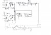
I changed C2 and C4 to the 100µF 100V NP (I assume that also means - + orientation no longer matter, although the diagramme specifies a + - side for C2) caps. I shorted Q7 E-C and did some tests.

ON, speaker voltage = 0.85mV roughly (no change there). R18 voltage = 0V

ON, speaker cables connected to speaker : R18 voltage = 5mV (still with Q7 shorted). Now, interestingly, Q10 heats up reasonably quickly, nothing excessive, it seems as if it heats up the way it should, i can keep touching it. HOWEVER - Q11 stays cold, or at least much colder that Q11...
Now, I tried releasing the Q7 jumper... Voltage shoots up to 60mV in a couple of seconds... I switched everything off.

In addition, in both cases (Q7 jumper ON and OFF), when connected to the speaker, the "thump" was greatly reduced on power up, hardly noticeable, so that's great - BUT, even with a source plugged in, nothing goes through... The speaker is completely quiet. The "AUTO" function works fine though : with the source plugged in, but not playing anything, the amp stays on standby, RED LED; with music playing (this is an mp3 player, not my home cinema amp), it goes green... Alas no sound.

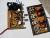
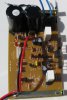
N.B. I have no C17, there is a section on my board where there are no components, although the markings are there JP8, Q17, C17, ZD5, C15, C16, ZD6, R29, R25, RJ1 (on the other side of the board). I guess those are for additional functionality that my cheaper version didn't have...
 
Last edited:
Let's do the pot thing and try to add a bias control. I will be a good idea in the long run.

Sounds good to me... All I need is the pot you mentioned earlier?

Let's also try to match Q1 and Q2 within 5-10%.

Sounds great, that'll take a bit of work, but sounds like fun. I'll get started when I get a couple of hours to look into it. We were posting in parallel (not in series, ha - we do as we can!), I've been describing some tests I did while you wrote this post.
 
Last edited:
News Flash - Is Q17, "MPSA13 NPN Darlington Transistor," bust?

I decided I'd test my old Q17 transistor, and found that it behaved as any other transistor, close etc, except for the following:
C-B = 0.64V
E-B = 1.16V

Now, I was expecting something a little higher for the Emitter - Base combination, but that much!

So, I removed my "current" Q17 and tested it. Turns out I get very similar readings. Is it because it's a darlington transistor, or are they both bust (in which case that could explain the ever increasing voltage at Q10-Q11..)?
 
Last edited:
The data sheet is here: **broken link removed** I didn't realize it was a darlington. I don't suspect it is bad. If you look at the symbol of a darlington, there are two diode drops from B to E.

Hmmm, I thought of that during the night, I guess a "darlington pair" doesn't have to be two, physically separate, transistors, and can be part of one "transistor package". Sad, was hoping to have found something critical.

Did you check the sub gain control?
Unfortunately, yes - played with volume and crossover

I need to recover (Got hit with a low blood sugar) a bit before I can make any sense out of what you said earlier.
Sorry to hear that; it's the weekend anyway, important to relax!
 
OK, I did some more testing. I also changed C1 and C10 to their improved version, on a separate little PCB bracket. Here are some results I found:

AUTO feature still works fine, with the source; gain and crossover turned to max, I can hear faint action from the speaker; maybe this was also true last night, it's hardly noticeable. What should be waking up a whole neighbourhood with windows trembling is reduced down to vibrations that would hardly scare a snake away (got to make the descriptions interesting!)

It seems that changing the C2 and C4 caps indeed had the effect of hugely reducing the "thumps" at startup, but by reducing the whole amplification output... Could this make sense? Maybe I could try reverting one back to the previous one, and test? Wish I knew more about electronics...

With the amp switched on, regardless of music playing or not, the speaker output voltage remains around 0.08V. Now... Interestingly (and scaringly), when I put the amp on stand-by (RED LED), the speaker voltage reduce to about 0.004V (great, I first thought), and then started increasing at a steady rate. I got up to 1100mV and then decided it was time to kill the AC, not knowing if this could potentially be dangerous... Could this also be due to the caps unloading?


On a side note, Q7 (the other issue here), was shorted at E-C for those tests. Once again, I briefly tried removing the jumper, and Q10 (especially) and Q11 got very hot, very quickly, and there was no change in output volume / speaker voltage. So for the moment E-C will stay shorted...
 
Now you have the hang of a few things: 75 mV or so is BAD for R18/R19. 0.75 V is bad for DC on speaker terminals. OV is GOOD, but not OK for E-C of Q7.

With Q7 shorted, what do you have across R11 and R12, R15, R16, R4, R5 and R9?

C2 would have a dramatic effect on thumps because it briefly shorts the audio signal.

There are two simple rules you have to remember:

1. The voltage across a capacitor cannot change instantaneously. (corrolary: initailly acts as a short with an impulse)
2. The current through an inductor cannot change instantaneously.

Another rule:

With a capacitor resistor series combination:

f=1/(2*pi*R*C); is a -3db frequency which defines the frequency response. -3db is about 70.7%
So R7, C4 governs the low frequency response
R1, C1; C1 is a coupling cap whose purpose is to remove DC


RC is known as the "time constant". At 5 * RC, your at about 99.9% (forget actual number) of the final value of an exponential.
 
Last edited:
Another thing:

A power amp consists of stages of voltage gain and current gain, thus you have in the end "power gain". Q8-Q11 are a darlington current gain stages.

The voltage between Q7(E) and Q7(C) should be around 2.4 Volts. This 2.4 comes from the B-E drop of Q8,Q10 of about 1.2 and the B-E drop of Q9, Q11 of 1.2V.

If the voltage is less than 2.4V then Q5 or Q6 are being driven differently or have different gains.

Comparing the voltages across R4 and R9 should off some insight with or without Q7 (E-C) shorted and so should the voltages across R11 and R12.

Just for fun, check the AC voltage across C19 and C18 and check the DC voltages across the individual diodes of BD1. I don't suspect any problems here.
 
I replaced C2 and C4 with their predecessors and tested audio again. The sub went back to "functioning" normally, with the thumping (Q7 shorted). I noticed Q10-Q11 heated up quite quickly still though, especially as I increased the gain, I could no longer touch them after a few seconds.

C2 is a flat, small, beige cap, but seems to have no capacitance according to the meter? Acts as "open" - but there again so does C6, which is identical, out of circuit. I don't understand this behaviour, because when I test any other cap with the DVM, I either get an accurate reading, or a "0L" when the capacitance is too great for it to measure, so for typical 100µF caps. But with C2 and C6 I get a reading very close to 0 instead of an error (in both polarities). Why is that? What sort of cap is this?

With Q7 shorted, what do you have across R11 and R12, R15, R16, R4, R5 and R9?
R11 = 0.56V (starts around 0.490V and increases as Q10 heats up)
R12 = 0.56V (same as above - voltage could continue increasing?)
R15 = 0.240V.... and keeps on increasing
R16 = 0.220V.... and keeps on increasing
R4 = 1.070V (ditto)
R5 = 1.103V.... and this one remains stable !
R9 = 1.072V.... this one increases.

So, interestingly, R11, R12, R15, R4 and R9 (NOT R5!) voltages increase as Q10/Q11 heat up. Now, if I cool Q10/Q11 down (cold air on them), the voltage reduces to get close to it's "start-off point". So their heating is fueling an increase in voltage... which could then, lead to an increase in their heating maybe? Either way I didn't want to try and leave it on too long without any heatsinks...

The voltage between Q7(E) and Q7(C) should be around 2.4 Volts. This 2.4 comes from the B-E drop of Q8,Q10 of about 1.2 and the B-E drop of Q9, Q11 of 1.2V.
Q7 E-C NOT shorted (quick measurements, Q10 gets boiling hot within seconds without Q7 E-C shorted):
Q7 E-C = 2.51V
R4 = 1.062V and increasing
R9 = 1.067V and increasing
R11 = 0.445V and quick increase
R12 = 0.445V and quick increase

Just for fun, check the AC voltage across C19 and C18 and check the DC voltages across the individual diodes of BD1. I don't suspect any problems here.
N.B. Q7 E-C shorted for those readings
C18 = 0.8V (AC) amp OFF
C19 = 0.9V (AC) amp OFF, C19 = 1.03V amp ON
Strangely, the DVM seems to really struggle picking up on the AC voltage. It keeps jumping between 0L and something around 0.8-0.9V roughly. It's very hard to get a stable reading for C19, and near impossible for C18. Does that make sense?
BD1 +- = 74.8V, DC (amp OFF)
BD1 - earth = 37.5
BD1 + earth = 37.5
earth to earth = 0.012 - 0.013V
 
Last edited:
I guess Oops. C2 is probably 100pf, not 100 uf and it's similar to C5 and C6. These would be ceramic capacitors and they are at the resolution of your meter, so you can't measure them. If C2 was 100 pf and replaced with 100uf, then I could see why the amp didn't work. If C2 were 100 pf, then the frequency response would extend to about 72 kHz.

C4, I think is an electrolytic cap of 100 uf.

The bias on Q7 is in the ballpark or is OK. Only real way to tell is to use the heatsink. Cure: bias control pot or heatsink.
It is normal for either Q8/Q10 or Q9/Q11 to be warm and the other one cold at idle.

So, except for the thumping, your back to square 1, but have learned a lot.

C5 and C6 are known as "speed up" capacitors in their application.

I'd expect the AC ripple to be jumpy unless you had a TRMS meter. That's OK.

I think the voltages look really good.

What if, the thumping is in the input rather than the amp?

Try grounding SG to GND at the connector and see if it thumps.

For fun, see if you can get a J174 FET and I'll see if what I have in mind (Cap, FET, Resistor) might work. It does depend on the SG to GND test working.

Another possibility is what looks like C16? (100 uf at 16V) in parallel with a 2.7 M resistor R43 should delay the MUTE signal on detection of audio. The last OP amp controlling MUTE is configured as a comparitor to 0.6 volts. C16/R43 does create a time constant. If C16 were open or had a low ESR, that might cause thumping. The voltage across R43 should rise when audio is applied. There should be a delay between when you apply audio and when the LED changes.

Switching gears: I got a "silt fence" delivered today for a spring/summer project.
 
I guess Oops. C2 is probably 100pf, not 100 uf and it's similar to C5 and C6. These would be ceramic capacitors and they are at the resolution of your meter, so you can't measure them. If C2 was 100 pf and replaced with 100uf, then I could see why the amp didn't work. If C2 were 100 pf, then the frequency response would extend to about 72 kHz.

C4, I think is an electrolytic cap of 100 uf.

In fairness, the schematic doesn't give any indication of units, just say "100"! 100nF... or 100pF... But clearly not µF, now we know! I can at least change C4, that one is 100µF.

The bias on Q7 is in the ballpark or is OK. Only real way to tell is to use the heatsink. Cure: bias control pot or heatsink.
It is normal for either Q8/Q10 or Q9/Q11 to be warm and the other one cold at idle.
I think a bias acontrol pot is in order. Without E-C shorted, Q10-Q11 literaly get smoking hot within 5-10seconds, even with a heatsink I don't see them surviving long. That wasn't originally the case. What happens if I just leave Q7 E-C permanently shorted?

What if, the thumping is in the input rather than the amp?
The thumps occur when I first switch on the amp from cold, i.e. when the switch is in the ON position (=green LED, potentially), and I hit the AC switch to ON. That happens regardless of source plugged in or not. Then, with the home cinema amp (which feeds DC), everytime I would pause, resume, change source, change channel etc, another thump would occur. Maybe this wouldn't happen if I fixed the DC current, but the initial startup thump is nasty and still occurs with no source unfortunately. Only happens when cold though; when I kill the AC, and switch it back on after a few seconds, it's fine.... But the longer I keep it off, the bigger the "thump".

Try grounding SG to GND at the connector and see if it thumps.
Will do when I get chance. Today and next few days are very busy with work, but I'll give that a go if I have a minute tonight.


For fun, see if you can get a J174 FET and I'll see if what I have in mind (Cap, FET, Resistor) might work. It does depend on the SG to GND test working.

Another possibility is what looks like C16? (100 uf at 16V) in parallel with a 2.7 M resistor R43 should delay the MUTE signal on detection of audio. The last OP amp controlling MUTE is configured as a comparitor to 0.6 volts. C16/R43 does create a time constant. If C16 were open or had a low ESR, that might cause thumping. The voltage across R43 should rise when audio is applied. There should be a delay between when you apply audio and when the LED changes.

Ditto - thanks for the advice!

Switching gears: I got a "silt fence" delivered today for a spring/summer project.

Different kind of work, indeed! Good luck with that.
 
That wasn't originally the case. What happens if I just leave Q7 E-C permanently shorted?

You get crossover distortion.

Look for a delay between applying music and having the LED turn on.

Drainage

Last summer I started a massive drainage project. Permissions, design, challenges, education and procurement of materials were all part of it. Digging under a 4 foot length of sidewalk to put a 4 inch diameter pipe was one of those challenges. Digging a trench 30 feet long, 18" deep and 10" wide was another. Basically I put in two catch basins, 30 feet of pipe (various types) and a pop-up emitter. For now, I need to keep the silt out of the pipes.

It works. There is no water in the basement, but it's only 1/3 complete. This summer it's 30 feet of this wierd pipe (4" diameter perforated corrogated drainage pipe wrapped in peanuts and a sock for a diameter of 10", 1 or 2 catch basins with a swale (shallow depression in the grass on top of the pipe). The challenge this year will be to keep the water out of the basement during construction.
 
Try grounding SG to GND at the connector and see if it thumps.

So, I've finally had a chance to do some testing. If I directly connect SG to GND, before it gets to C1, the thumping disappears. However, there is a pronounced mains hum. Is this good?

For fun, see if you can get a J174 FET and I'll see if what I have in mind (Cap, FET, Resistor) might work. It does depend on the SG to GND test working.

What would the J174 FET do? It seems to be another transistor?

I'm still planning on getting a 500 ohm 3/4" trimpot when I get a chance.


Another possibility is what looks like C16? (100 uf at 16V) in parallel with a 2.7 M resistor R43 should delay the MUTE signal on detection of audio. The last OP amp controlling MUTE is configured as a comparitor to 0.6 volts. C16/R43 does create a time constant. If C16 were open or had a low ESR, that might cause thumping. The voltage across R43 should rise when audio is applied. There should be a delay between when you apply audio and when the LED changes.

C16 is inexistant on this board. The PCB has a place for it, but as the picture attached shows (old picture, been some cap changes etc since !), there is room for it, along with C15,17 R28, ZD5 etc, but no components there. I wonder what happens if I "add" those bits in !

How's the silt project going? Sunny weather where you're based? Beautiful sunshine over in Europe lately...
 

Attachments

  • IMG_2580.JPG
    IMG_2580.JPG
    1.6 MB · Views: 470
Hum is OK.
A J174 is a Field Effect Transistor with interesting properties. Back burner.
500 POT would be good.

The components your talking about, I can't read the type designations on page 1 of the schematic so you'll have to describe their locations by describing where on the schematic page they are located or make a page and circle them. You can use the free program www.irfanview.con and convert the page to .jpg and then use MS Paint to annotate. IRfanview requires the downloadable plug-in set to open PDF's.

I can't read the part numbers on the 1st sheet so here goes.
Find the center terminal of the switch.
Locate the 100 uf and large value resistor (2.x m-ohm) off of that terminal.

What is the OP amp type # that it's connected too?

The voltage across the parallel combination is what I'm after; call it Vdelay.
There is a 1n4148 diode nearby. What is the voltage across it (Vdiode-ref) with or without sound?

OK.

Test #1
Check voltage across diode. Power on. Sound doesn't matter. If zero, check diode. I would not use a 1n4148 here. Voltage should be between about 0.4 and 0.6 volts.

Test #2.
Place sub in auto mode.
Apply sound. Note delay when LED changes color. Delay should not be zero.

test #3
Look at the voltage across the cap, as you apply audio. Use a fixed voltage scale on your meter, not auto-range.
Look at this voltage when you apply music. It should steadily increase.

You might try temporarily substituting the 100 uf cap, since you can't measure it if the diode has a decent voltage across it.

Since you have a spare ZD5 (5.6V), you could also try replacing the 1n4148 with 5.6 V Zener, but reverse the polarity. You would then have 5.6 V across this diode instead of 0.4 to 0.6 which should increase the delay.

I'm in the US (east coast), about a 4hr time difference. It's been rainy and it's been messing with the DSL and phone line. No dial tone/DSL for about 6 hrs yesterday. Today was the 3rd repair attempt and it's been referred to the "cable splicers". Lately, been working on income taxes. I did replace the landscape fabric with drainage fabric, but I was surprised at the retention time. I won't actively start digging for another 4 weeks or so. Trying to get grass to grow in a few places. High temperatures have been in the 50's (F) for the most part. We had one 75 deg F day so far.
 
The components your talking about, I can't read the type designations on page 1 of the schematic so you'll have to describe their locations by describing where on the schematic page they are located or make a page and circle them. You can use the free program www.irfanview.con and convert the page to .jpg and then use MS Paint to annotate. IRfanview requires the downloadable plug-in set to open PDF's.

I was referring to the missing components on the first PCB, the one we have been working on until now. I cropped the picture and circled the "missing" C16 etc, see attachment.

I can't read the part numbers on the 1st sheet so here goes.
Find the center terminal of the switch.
Locate the 100 uf and large value resistor (2.x m-ohm) off of that terminal.

What is the OP amp type # that it's connected too?

The voltage across the parallel combination is what I'm after; call it Vdelay.
There is a 1n4148 diode nearby. What is the voltage across it (Vdiode-ref) with or without sound?

This is on the second PCB, with the inputs/outputs, pots etc? Not sure what you are referring to here, I'll keep thinking about that.


Test #2.
Place sub in auto mode.
Apply sound. Note delay when LED changes color. Delay should not be zero.

This is one thing I can already comment on - there is NO delay when the LED switches colour on auto mode...

Could we be looking at something else bust on the second PCB?
 

Attachments

  • IMG_2580_Missing-components.jpg
    IMG_2580_Missing-components.jpg
    927.8 KB · Views: 458
Last edited:
So, I carried on with some testing, since I found some spare time today, thankfully ! I reassembled the PCB onto the heatsink, with thermal conducting paste, and switched the thing on without Q7 E-C shorted. A couple of unfortunate observations:

1. The heatsink struggled to dissipate the heat, and it's a huge aluminium plate... Within 2-3min, it got so warm is was nearly "untouchable" (I couldn't leave my fingers on the heatsink more than a few seconds); so I didn't wait for the transistors to burn again, and switched the thing off. Within 1-2min the heatsink was back down to mild/cold. So my heatsink is doing a great job at dissipating heat, but is no longer sufficient! Clearly something is still very wrong somewhere, but I have no idea what, or where...

2. Q8 and Q9 were also very hot.

3.1 The thump still occurs, when the amp is switched on from cold (straight from nothing to green LED). It doesn't do it when the amp is on stand-by mode when the AC power is switched on, and then switched onto forced on mofe (green LED), i.e. if I leave the red light to show up when I hit the AC switch, and then force it on (green), it's fine.

3.2 The thump doesn't occur (or possibly is diminished) when a source is plugged in, playing music, and I do the same routine (amp forced on ON mode and I hit the AC power switch).

4. I still have a small hum going through to the speaker when it's on, I assume this is because the output voltage (with no source plugged in) is still around 0.080 - 0.090V, not great... I also wonder how I could possibly decrease this, although fixing the other issues might be of greater importance !

I've changed quite a few bits of this PCB, going to make notes of what I have and haven't changed so far... Have been learning a hell of a lot, got loads of fancy tools, improved my soldering considerably (25W soldering iron really helped, my old 15W was a real nightmare), but I'm still stuck with the original problem + the one I created shorting things out !

Could it be possible the other PCB is responsible? I'll let you know what I haven't changed on PCB1 !
 
Last edited:
1. Putting in a bias Pot should fix that. The manufacturer probably selected transistors based on gain. Setting it is easy. You can check the range acrooss E-C; probably 2.0 through 2.4 volts. I'll usually start by adusting for 10 mV across the fusible resistors and watch it when the amp is idleing so it doesn't significantly drift higher in value.

2. One or the other side should be "warm", not hot.

3. Based on the circuit of the pre-amp, there should be a delay.

4. You need to short the source input with a resistor to be a valid test for hum. The closer the Hfe of Q1 and Q2, the better the hum rejection. Is your measurement an AC voltage?

5. I think there is something wromg with the turn-on delay in the other board (preamp/control).

So,

A) I think the manufacturer selected components. The bias pot should fix that.
B) There should be a delay based on the circuitry I see in the preamp/control board.

If you look at the preamp/control board. Lower right hand corner. Follow to the left the MUTE signal.

MUTE goes to the LED and Pin 7 of the OP amp.

Locate the input of the OP amp:
1. Now the diode (1n4148) and series resistor (unknown value and designation)
2. Locate the 100uf cap and the 2.x M resistor

That's the area I want to go next. Keep Q7 (E-C) shorted. Ket a 3.3K and 500 ohm variable resistor (10 Turn trimmer preferred)
 
Try this pic to make things a bit easier to understand.

The voltage should increase across the capacitor starting when audio is detected. Use
You meter on a fixed range. Don't autorange. You have a 100 uf cap to substitute here
because you can't test it with your meter.

When the voltage reaches the reference of the 1n4148 diode ( a diode drop), the LED should turn on. We can increase the diode drop and thus increase the delay. You have a 5.6 V diode, but it has to be turned around to provide 5.6 V. Otherwise it would provide 0.6 V or a standard diode drop.

Verstehen Sie?
 

Attachments

  • AMP turn on delay.tests.jpg
    AMP turn on delay.tests.jpg
    30.6 KB · Views: 422
Verstanden, ich glaube - danke!

I have also starting making a clean jpg of the messy map, so we can see clearly what's what; based on schematic, PCB layout and measurements. Might be a few inaccuracies, I can fine tune as we go along (luckily not exactly launching a space shuttle into space with this). So far I mainly focused on the bottom section, seems more critical here...

I'm going to run those tests, and build up a list of parts to get this afternoon (trimpot, spare caps, etc)

Try this pic to make things a bit easier to understand.

The voltage should increase across the capacitor starting when audio is detected. Use
You meter on a fixed range. Don't autorange. You have a 100 uf cap to substitute here
because you can't test it with your meter.

When the voltage reaches the reference of the 1n4148 diode ( a diode drop), the LED should turn on. We can increase the diode drop and thus increase the delay. You have a 5.6 V diode, but it has to be turned around to provide 5.6 V. Otherwise it would provide 0.6 V or a standard diode drop.

Verstehen Sie?
 

Attachments

  • Eltax-Atomic-A10-2_DEL.jpg
    Eltax-Atomic-A10-2_DEL.jpg
    553.8 KB · Views: 727
Status
Not open for further replies.

Latest threads

Back
Top