If there is something that is stopping one channel from working, or makes it a lot quieter than the other channel, it might not be the balance control.
View attachment 124900
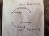
This is the circuit diagram that I found online.
The balance control seems to be a linear stereo 100 kOhm potentiometer. If you can find any linear, stereo 100 kOhm potentiometer that fits, you could use that. Although the diagram has two separate part numbers for VR501 and VR502, the parts list says they are one item. A stereo potentiometer is just two potentiometers controlled by a common shaft.
If you want to bypass the control, you could just fit four 50 kOhm resistors. You would need one from each slider to each end.