Continue to Site

Welcome to our site!

Electro Tech is an online community (with over 170,000 members) who enjoy talking about and building electronic circuits, projects and gadgets. To participate you need to register. Registration is free. Click here to register now.

  • Welcome to our site! Electro Tech is an online community (with over 170,000 members) who enjoy talking about and building electronic circuits, projects and gadgets. To participate you need to register. Registration is free. Click here to register now.

High resistance AC actuator motor reverse direction by applied force

Status
Not open for further replies.

Meta_Alchemy

New Member
Hello,
I am trying to repair a washing machine actuator motor. This actuator is responsible for wash and spin cycle. It is motor moves a plastic arm in one or the other position. The computer sends a signal to the motor to be either at one or the the other position. Since the motor itself only moves in one direction, it is the plastic gears inside that will reverse direction when it can't go any further. I guess it is by sheer mechanical force. I just don't understand how this plastic gears reverse when it can't rotate in one direction anymore.

I took one apart to see what I find, nothing but just 6 little plastic gears. If need be I can take it apart again to show them plastic gears again.
Thanks in advance for any help you can provide.
The motor in mine does not reverse. Instead of reversing it keeps clicking.
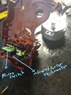
This is the motor

1637041547043.png


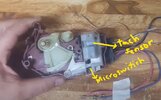
Below shows the plastic arm that is attached to the motor shaft. Notice the plastic arm on the lft maxed out, the arm can not go clockwise anymore. It will have to reverse direction if it has to move again.
1637041769208.png


This picture below shows the plastic arm at its other end of travel. It can not go counterclockwise anymore. So it will be force to reverse direction if it has to move again.

1637041905191.png
 
Welcome to ETO.

Would replacing the entire motor module be out of the question?
An appliance repair depot may have a replacement, either a brick and mortar store or an online dealer.
 
It looks to be a similar concept to central heating water valves?

Those just apply power continuously to the motor to run the actuator to one limit against a spring, then it stays at that point, stalled.
When power is removed, the spring on the driven quadrant "unwinds" and causes the motor to run backwards, so the actuator returns to the start position.

With that type, the motor has an attached gearbox & output pinion, and the quadrant gear is the only external part, other than what that rotates (eg. a valve spindle).

The official cure for a failed one is to replace the motor/gearbox assembly; however it's often just that the grease in the gearbox has "set" over time and the spring can no longer reset the device. In that case, cleaning and re-lubricating the gearbox can add a few years of life.

eg. A typical one - the majority of types use the same pattern unit, just different connections on the ends of the wires.


If yours can move in both directions but does not reset itself, it may be that the spring has broken?
Should it have a tension spring attached to that white peg, or a spiral spring around the centre of the white quadrant?
 
I suspect that there could be a solenoid under the translucent cover on the right hand side. I think it could be basically as rjenkinsgb describes but in the powered position it is latched in that position when the motor power is removed. I think the solenoid (If there is one.) is pulsed to release the latch and it is returned by a spring.
A WELL FOCUSED picture with the translucent cover removed may help us to understand how it is designed to work.

Les.
 
Searching for the motor part number brings up a vast selection spare motors and complete similar units, apparently called a "shift actuator".
They start at around £20 / $30

Some of the photos are a pretty good; eg. the one below, though it's reversed.
Looking at the two grooves and ramp in the quadrant, I think there may be another possibility - something like a push-push mechanism (like a retractable pen) and switch contacts under the right-hand cover.

eg. To operate it, the motor runs the quadrant so far and disconnects one contact, that fed power to select that position; it stops but is latched by the side cam/peg.

For the "release" operation, power is fed by a second contact only operated in the upper half of the movement, while the cam is engaged with the quadrant track; the motor runs (still the same way) and moves the quadrant around further until the cam peg drops in to the other track and disconnects that power feed contact - so the quadrant spring makes it run back to the start position.


714B76U5jRS._AC_SL1500_.jpg
 
That looks like it's a synchronous motor, similar to the ones in mains powered clocks. The only mains clocks that are still common are timer plugs like these:- https://www.ikea.com/gb/en/p/taenda-timer-24-hours-indoor-earthed-white-10445765/

Synchronous motors like that will run in either direction, and will often reverse when they hit an obstruction.

Clocks have to have a reversing device, some of which literally put an obstruction in the way of the motor if it runs backwards. In this actuator, the designers seem to have used the reversing feature to their advantage.
 
I was wrong about there being a solenoid under the cover. I think I can see a missing tooth on the final drive gear in your second picture in post #6 Can you take a picture of the top plate looking directly down on the inside of the top plate so we can get a better view of the final drive gear. Most of your pictures are still out of focus. If your camera does not have a macro setting just get as close as you can while the image is still in focus. Setting the camera to a smaller aperture (Higher f number.) may help with the focusing but would then require a slower shutter speed so you then may have to find a way to hold the camera steadier using a tripod etc.

Les.
 
That looks like it's a synchronous motor, similar to the ones in mains powered clocks. The only mains clocks that are still common are timer plugs like these:- https://www.ikea.com/gb/en/p/taenda-timer-24-hours-indoor-earthed-white-10445765/

Synchronous motors like that will run in either direction, and will often reverse when they hit an obstruction.

Clocks have to have a reversing device, some of which literally put an obstruction in the way of the motor if it runs backwards. In this actuator, the designers seem to have used the reversing feature to their advantage.

Looks just like a turntable motor out of a microwave oven.
 
Why is the outer gear missing a tooth?
 
Les Jones , there is indeed more than one tooth missing under that output shaft. But that wasn't the cause of not making a turn after the stops. I broke a tooth in two spots by force turning it so I can remove the motor.
To be honest I figured I sacrifice one just to take it apart. The other one just as it barely got out of lock end, I unpluged the power so I was able to remove it without destroying any teeth.
Typically it is the microswitch in them that go bad.
I have never had to replace the tech sensor or the motor. Of the half a dozen dead ones I had accumulated, I repaired 4.
This is the first time I noticed a bad motor and two of them. Also the one with busted teeth also have issue with the tech sensor. The demeanor in the other motor hasn't changed.
All in all I was just wondering how in the world these motors turn around. It appears it is nothing but force stop that make them turn around. I just can't picture it in my mind's eye.
I have seen the other kinds on youtube how they turn around, the design in the gear shows how they work. The motor just go in one direction and the gear engages with a different gear at certain degree of rotation. It is celever alright.
But these motors I can't get a mental picture. It appears to me that when the gears don't move the gear on the shaft of the motor also stop. And it of course stops the motor. This causes the motor to probably have some kind of reversal with the field of the coil, just enough of a polarity conflict that the motor is pushed the other way within the coil of wire.... something along that concept... "however thought of that". Then the motor actually turns around and that causes the gear to turn in reverse. It is not that the gear reverses the motor. It is the motor that goes,,, hey forget this I am turning around if I can't go that way...
I can just picture that dog gone thing having an internal dialogue.... " you trying to stop me.. I don't think so. I just keep going in the opposite direction". :)
 

Attachments

  • Actuator parts identifcation.jpg
    Actuator parts identifcation.jpg
    727.6 KB · Views: 195
  • InkedMicroswtich swtich location id_LI.jpg
    InkedMicroswtich swtich location id_LI.jpg
    925.9 KB · Views: 216
Last edited:
Why is the outer gear missing a tooth?
Good eyes there. Because I forced the plastic arm backwards while it was running to give it a helping hand. I guess it wasn't happy about that as I heard the gears grinding teeth. I busted two teeth, the other you can't see. I figured that should reverse it by definition, the same as running into an obstacle. I guess not.
 
Can you post photos of the other parts?
eg. The outside of the quadrant and the part that rides in that slot?

Also, is there a spring trying to hold the quadrant to one end?

And ps. Is there a resistor and/or diode in the end part with the microswitch?
 
I managed to save another one of the remaining two, combining what appeared to be the better gears. I don't know how to put a short video of it here but in couple of pictures.would this video link work?
 

Attachments

  • Repaired one of the two remained.jpg
    Repaired one of the two remained.jpg
    904.1 KB · Views: 190
  • Repaired one of the two remained 2.jpg
    Repaired one of the two remained 2.jpg
    1.4 MB · Views: 190
Last edited:

rjenkinsgb

I just realized why the motor can't reverse once it reaches the ends. The fact of the matter is it doesn't truly reach the end. Why?
Because when it reaches the end, the plastic gears are too worn to truly stop the motor so it is actually still going forward. When I ran the motor on the bench, it would try to back out but just clicking or so I thought. The truth of it is the clicking sound does not mean it is trying to back out and it can't, that won't make sense, it means it is still going forward. It means the plastic gears are slipping and not truly stopping the motor.

So the only repair is new plastic gears and that is another story. And that is my diagnostic for this.
 
Last edited:
Can you post photos of the other parts?
eg. The outside of the quadrant and the part that rides in that slot?

Also, is there a spring trying to hold the quadrant to one end?

And ps. Is there a resistor and/or diode in the end part with the microswitch?
The motor turns independent of the rest. The computer sends 120VAC to the motor temporarily moving that plastic arm. That free end of that plastic arm ( if you notice in the picture) goes into the clutch on the machine. So the clutch either moves up ( disingaging another plastic gear) from turning the basket or it the other way around from up position to down position. The microswitch does not play directly on the motor operation. And the slot of the actuator fits inside the casing of the transmission. There is a round gear like mechanism with slots cut in it. It opens and closes the path of the beam of the sensor.
 
Status
Not open for further replies.

Latest threads

New Articles From Microcontroller Tips

Back
Top