Continue to Site

Welcome to our site!

Electro Tech is an online community (with over 170,000 members) who enjoy talking about and building electronic circuits, projects and gadgets. To participate you need to register. Registration is free. Click here to register now.

  • Welcome to our site! Electro Tech is an online community (with over 170,000 members) who enjoy talking about and building electronic circuits, projects and gadgets. To participate you need to register. Registration is free. Click here to register now.

High Pass Active Filter 4th - Sallen Key A=1 - Bessel approximation

Status
Not open for further replies.

jeremieblanc

New Member
Hello,

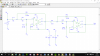
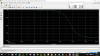
i have problem with simulation model (PSpice) - high pass active filter 4th, sallen key, bessel approximation. I need a graph of the phase shift and i always used to function P(V(name)). For Low Pass filter (3,4,5.....row) and High Pass (2 row) all is OK. For this model i calculate +120 phase shift for 1 kHz. FilterPro also gives this value, but pspice give -240 deg. If i write P(V(Vout))+360 or P(V(Vsr))+P(V(Vout)/V(Vsr)) (first stage + second stage) i had good graph. Maybe somebody know why PSpice give me wrong result ???
https://imgur.com/a/J4K2n
 
Welcome,

Try it first with an "ideal" opamp, instead of that 40 year old toy. To make this filter work, you simulate first using an opamp with a higher GBP... Once the circuit simulates with an "ideal" opamp, you can try some modern opamps...

And next time, post your graphics here. I resent having to look at all the b.s. advertising at Imugr...
 
Last edited:
MikeMI thanks for your answer and comment (I apologize for the photos). I try with "ideal" opamp when i leared realized a lower rows - differences only for a high frequences where "real" opamp have limiting factor (ratio - amplification*bandwidth) and you have to use vdc +15/-15 to power opamp. So that is wrog clue,contemplation.
 

Attachments

  • górnoprzepustowy4rzedu.png
    górnoprzepustowy4rzedu.png
    57.3 KB · Views: 165
  • goodandwrong.png
    goodandwrong.png
    48.6 KB · Views: 270
  • filterpro.png
    filterpro.png
    185.4 KB · Views: 159
Using LTSpice and ideal opamps with a GBP of 1e7:

371.png


If I set the GBP of the two opamps to 1e5, then it changes the phase shift...
 
Last edited:
Thanks for your answer and time. In PSPice OP have gain 1e6 when i change to 1e5 or 1e7 nothing changes with graph :( 
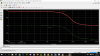
1kHz = -240. I made 5th HP filter and the same problem. Also when i used to ideal opamp for 5th filter and function which give me good graph for real opamp, PSpice give me wrong graph - same like P(V(Vout)).

4th -
real opamp - P(V(Vout) - wrong graph
real opamp - P(V(Vsr)/V(Vin))+P(V(Vout)/V(Vsr)) - good graph
ideal opamp - P(V(Vout) - wrong graph
ideal opamp - P(V(Vsr)/V(Vin))+P(V(Vout)/V(Vsr)) - good graph (independently from GBP)
5th -
real opamp - P(V(Vout) - wrong graph
real opamp - P(V(Vind)/V(Vin))+P(V(Vind2)/V(Vind))+P(V(Vout)/V(Vind2)) - good graph
ideal opamp - P(V(Vout) - wrong graph
ideal opamp - P(V(Vind)/V(Vin))+P(V(Vind2)/V(Vind))+P(V(Vout)/V(Vind2)) - wrong graph (independently from GBP)
 

Attachments

  • ideal4.png
    ideal4.png
    64.6 KB · Views: 158
  • ideal4phase.png
    ideal4phase.png
    55.2 KB · Views: 146
  • ideal5.png
    ideal5.png
    54.3 KB · Views: 147
Are you plotting Gain = V(out)/V(in)?

I re-ran the LTSpice sim as a frequency sweep from 1Hz to 1e6Hz. I asked LTSpice to plot the Phase of V(out) in real degrees, since by default, V(in) is 1V@0degrees.

Note that the Ph() plot function in LTSpice takes the Phase modulo(360degrees). However, it would also be correct to say that the phase is 120.8 + n*360 degrees, where n is an signed integer.

371p.png
 
Last edited:
MikeMl once more thanks for your response and time (you are good man) .I mostly think that when i use some function it will show a good result (of course if schematic is made good). I learned at the University that we should always check us graph and try as far as possible interpreted it but here i can only describe my problem and tell how we can - in this case- make good phase shift graph P(V(Vout)/V(Vin))+360 for PSpice. Unfortunately at this stage of master thesis i can't show that LTspice handles with this simulation much better because it would change the design assumptions (but I think it would be a great complement to its:p). Thank you for advice and learning from you.
 
Status
Not open for further replies.

Latest threads

New Articles From Microcontroller Tips

Back
Top