Continue to Site

Welcome to our site!

Electro Tech is an online community (with over 170,000 members) who enjoy talking about and building electronic circuits, projects and gadgets. To participate you need to register. Registration is free. Click here to register now.

  • Welcome to our site! Electro Tech is an online community (with over 170,000 members) who enjoy talking about and building electronic circuits, projects and gadgets. To participate you need to register. Registration is free. Click here to register now.

high gain amplifier

Status
Not open for further replies.

bogdanfirst

New Member
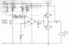
does anybody have a schematic for listening to sounds trough walls?
i probably need a high gain amplifier, something with low noise....
i might need it to be able to hear what people are saying at far distance, but for this i need a parabolic dish right?
i know there are devices that are already buid and they do that, but i cant find one here and where is the fun if i dont build it?
 
Yes I do have that schematic but its drawn in my collection book and I'll have to scan it. It consists of 741 condenser mic amp. followed by LM386 audio amp. The condenser mic is fitted into a big funnel for better response and directivity.
 
please....
i have build something useing 2 LM307(dual op-amp) amps(i think) but i am not satisfied with it. too much noise and i hear all in the headphones.
 
Hi bogdan,
I found the book and I have scanned the circuit.
Code:
Parts List:
--------------
R1	= 3.3k
R2 	= 4.7k
R3,R4	= 10k
P1	= 2.2M
C1	= 47nF
C2	= 10uF/25V
C3	= 220uF/25V
C4	= 1000uF/25V
Q1	= AC187
Q2	= AC188
IC1	= 741
 

Attachments

  • AMP.jpg
    AMP.jpg
    35.8 KB · Views: 1,331
You can try it but I think the transistors will give a good current boost which is better than LM386.
 
This is not a Hi-Fi equipment,and very old with germanium output stage.I don't understand the C2 on the opamp. output.PNP and NPN base direct connection make high distortions.
Just idea: when You scanned from transparent paper, cover the back with black paper to avoid the reflection from white scanner cover.
 
This is not scanned from a transparent paper. Its drawn on a notebook paper and the imprint you see behind is of other schematic drawn on the other side of the page.
This circuit is not at all meant for professional use. It is for hobbyists.
 
but where do you think i will find AC transistors? not found here anymore .. they are Ge right? what can i use in place of them? something from the BC or BD series....2N transistors are quite hard to find...
 
I guess you can use BD139 instead of AC187 and BD140 instead of AC188. These are not exact replacements but I think they'll work. Right now I am not able to find my transistor selector book, I'll post the replacements as soon as I find it or may be some one can post it if he knows.
 
yes i think that they are appropiate.....
1A will be enough.....
i see the ACs hold 1A too...with beta>65...
o, by the way, what difference is between the AC180 and AC180K ?is it that one has a device attached to is for mounting on the heatsink....?
 
kinjalgp,

I don't think the circuit will work with a 741. Pin 3 is an input to a bipolar transistor which requires a forward bias. There is none in your circuit.
 
??? :shock:

The 741 is wired in inverting amplifier mode. What BJT are you talking about? Is it the one which forms the first differential amp. stage of 741? It is not necessary to forward bias the transistor of a differential amplifier.

Well, whatever may be the case, this is a standard inverting amplifier configuration with very high gain which works!
 
i see that the non-inverting pin 3 is connected to the ground wich i see no problem here......
if it was the inverting input to the ground that would mean that the output will be high wich will be a problem, but in another circuit.
 
kinjalgp said:
??? :shock:

The 741 is wired in inverting amplifier mode. What BJT are you talking about? Is it the one which forms the first differential amp. stage of 741? It is not necessary to forward bias the transistor of a differential amplifier.
Yes, I'm talking about the first input stage. Since when does a bipolar differential amplifier require no biassing?

Take a look at the data sheet. The non-inverting input feeds into a long-tailed diff. amplifier. I'd like to know how Q1 can conduct when its base is at the same potential as the negative rail.

https://www.electro-tech-online.com/custompdfs/2003/03/LM741.pdf
 
Yes , thats a mistake. But let me tell you that this is not my design. I had copied it from some projects book when I was in school.
The modification required is: Connect R3 to pin 3 insted of pin 2. This will raise the NI terminal to 4.5V and thus the op-amp. will give ac output swing from 0-4.5 and 4.5 to 9V where 4.5 being the reference level.
 
Status
Not open for further replies.

Latest threads

New Articles From Microcontroller Tips

Back
Top