Continue to Site

Welcome to our site!

Electro Tech is an online community (with over 170,000 members) who enjoy talking about and building electronic circuits, projects and gadgets. To participate you need to register. Registration is free. Click here to register now.

  • Welcome to our site! Electro Tech is an online community (with over 170,000 members) who enjoy talking about and building electronic circuits, projects and gadgets. To participate you need to register. Registration is free. Click here to register now.

High Frequency Triangle Wave Generator

Status
Not open for further replies.

franz k

New Member
Dear all,

i want to build a very high frequency Triangle Wave generator.. My target is frequency of 36MHz and amplitude from 0V ~ 5V..
initially i want to use a DDS chip like AD9834 which capable of generating triangle wave..
however its max speed was only 75MSPS..

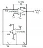
so my idea was to use opamp circuit as in TI documentation slau508 (refer to attached file)

according to my calculation , it needs opamp bandwidth 19 * 36MHz = 684MHz
and slew rate min of 360 V/us..

is my calculation correct?

i'm confused, because my simulation using LTSpice and LT1226 (GBW 1GHz, Slew Rate 400V/us Opamp) , the result was different
it only achieve around 8MHz triangle wave with bad triangle waveform..

thank you
 

Attachments

  • opamp triangle wave.JPG
    opamp triangle wave.JPG
    13.7 KB · Views: 817
I have been doing a lot of work on this recently. You really need a switching npn differential pair with the collector of 1 npn driving a current source of 1/2 the value of the differential pair current source. You need good high frequency transistors for your current sources and differential pair.
 
5Vpp at 38MHz triangle /\/\/\/ is 10V/38M = slew rate = 0.28V/us = 360ns/V ( not V/ns )

The bandwidth depends on your tolerance to signal error.

Can you define that in measurable terms? Linearity error? Peak rounding error? RMS error?
What load are you planning? 50R?
5% linearity is easy. <1% linearity is hard. What's this for?

Until then...
I would consider up to the 9th harmonic or a 3dB BW of ~360MHz BW as a starting point.

Bandwidth of triangle waves has the same odd harmonics as a square wave except attenuated by 6 dB per octave from integration.
So an ideal square wave and integrator with a lower capacitance load.


To stay well below current limit of Op Amp such as 30mA the maximum capacitive load at this slew rate from Ic=C*dv/dt
or C <=30mA * 360 ns/V = 0.01uF max ok.
 
I can get around 0.2% linearity at 0.2vp-p, but the need to amplify does naturally increase non linearity.
 
I can get around 0.2% linearity at 0.2vp-p, but the need to amplify does naturally increase non linearity.

Small signal is easy. But 5Vpp 1% linearity is hard. So specs on MUST HAVEs need to be defined.

Perhaps with suitable RF layout, one can generate this with 1.5GHz GBW will give one a gain of 5 at 300MHz

- limited to samples in USA only unless you want to buy 98 pcs at $1.83 budgetary price
AD8000
1.5 GHz, Ultra-High Speed Op Amp with Power-Down
 
The AMP I suggested is CFB
But what I meant is if you start with a 50 Ohm clock driver and drive a capacitor with to 5% of full scale (250mV) , wouldn't you get very low error? To buffer you need a BW to include 9 or 11th harmonic to capture signal content -46db for signal integrity of 0.25% ??
 
Welcome to ETO, franz k!

There is a previous thread here that may help: https://www.electro-tech-online.com/threads/200-mhz-triangular-wave.138704/

hi cowboybob,
thanks for the warm welcome.. i'm just join this forum since i think that it has many active gurus :)
i already read that post but still cannot found what i'm looking for

I have been doing a lot of work on this recently. You really need a switching npn differential pair with the collector of 1 npn driving a current source of 1/2 the value of the differential pair current source. You need good high frequency transistors for your current sources and differential pair.

hi moffy,
thanks for your responds.. do you ever try to use high performance op amps (high bandwidth and high slew rate) ?
recently i'm still doing on simulation using LTspice.. but sooner i will test the real circuit..


5Vpp at 38MHz triangle /\/\/\/ is 10V/38M = slew rate = 0.28V/us = 360ns/V ( not V/ns )

The bandwidth depends on your tolerance to signal error.

Can you define that in measurable terms? Linearity error? Peak rounding error? RMS error?
What load are you planning? 50R?
5% linearity is easy. <1% linearity is hard. What's this for?

Until then...
I would consider up to the 9th harmonic or a 3dB BW of ~360MHz BW as a starting point.

Bandwidth of triangle waves has the same odd harmonics as a square wave except attenuated by 6 dB per octave from integration.
So an ideal square wave and integrator with a lower capacitance load.


To stay well below current limit of Op Amp such as 30mA the maximum capacitive load at this slew rate from Ic=C*dv/dt
or C <=30mA * 360 ns/V = 0.01uF max ok.

dear tony

thanks for your responds :)
i'm planning to build a fast PWM signal.. so this triangle signal output will be feed into high speed comparator together with sine wave signal..
so i need a good triangle signal..

i also plan to use AD8000 opamps for my circuit as you mention.. do you think it can make a good triangle signal?

before i build the real system, i was simulating it using LTSpice with LT1226 ..
but i found that the resulted signal is very bad and cannot reach 36MHz..
 
38 MHz is the frequency, so the one-cycle period is 26.3 ns. But this is a symmetrical triangle wave, so the slew rate period is 1/2 the cycle period, making the slew rate 10 V / 13.16 ns, or 1 V / 1.316 ns, or 760 V/us.

ak
 
38 MHz is the frequency, so the one-cycle period is 26.3 ns. But this is a symmetrical triangle wave, so the slew rate period is 1/2 the cycle period, making the slew rate 10 V / 13.16 ns, or 1 V / 1.316 ns, or 760 V/us.

ak
But the voltage is 5V peak to peak.
 
38 MHz is the frequency, so the one-cycle period is 26.3 ns. But this is a symmetrical triangle wave, so the slew rate period is 1/2 the cycle period, making the slew rate 10 V / 13.16 ns, or 1 V / 1.316 ns, or 760 V/us.
In 26nS the voltage goes from 0 to 5 and back to 0. So 10V in 26nS
OR
0 to 5V in 13nS so 5V/13nS

I get 380V/uS. If you want good linearity the speed of the amp needs to be MORE than the speed of the signal.

If you want 0 to 5V output. Then you need a -3V and +7V supply or something below 0 and above 5V. You can't use a R-R output amp. It looks like you need a 12V amp.
 
Because you are using LTSpice I looked at Linear and they don't have fast amps that will work above 5 volts supply.
 
I misread an earlier post and thought the requirement was for 10 Vpp. oops. Even at half the slew rate, this smells like a current-feedback opamp application.

ak
 
....................
i'm confused, because my simulation using LTSpice and LT1226 (GBW 1GHz, Slew Rate 400V/us Opamp) , the result was different
it only achieve around 8MHz triangle wave with bad triangle waveform..
Post your .asc LTspice file.
 
hi moffy,
thanks for your responds.. do you ever try to use high performance op amps (high bandwidth and high slew rate) ?
recently i'm still doing on simulation using LTspice.. but sooner i will test the real circuit..


I tried simulating with high speed opamps, the best I used was the ADA4817, it's really nice, but you end up with ringing artifacts at the switching point, and a small square wave at the inverting node. All of these are distortion artifacts. It's pretty good but not as good as what I wanted, so I went open loop for the triangle generation. With the configuration I mentioned you get super clean rectangular current pulses that are very flat i.e. low distortion. The waveform looks very clean. It all depends on how you deal with the non linearities of the circuit. It's the detail that's important, how you buffer the triangle wave in the open loops case is super important.
 
Because you are using LTSpice I looked at Linear and they don't have fast amps that will work above 5 volts supply.

actually i don't need 5Vpp.. -1.5V ~ 1.5V is OK..

Post your .asc LTspice file.

please refer to attached file for the asc file..
i simulate using LT1226 (Slew Rate 400V/us , GBW 1GHz) , but the result was bad
the triangle signal was contaminated with sine wave.. and the freq of triangle was only below 10MHz

I tried simulating with high speed opamps, the best I used was the ADA4817, it's really nice, but you end up with ringing artifacts at the switching point, and a small square wave at the inverting node. All of these are distortion artifacts. It's pretty good but not as good as what I wanted, so I went open loop for the triangle generation. With the configuration I mentioned you get super clean rectangular current pulses that are very flat i.e. low distortion. The waveform looks very clean. It all depends on how you deal with the non linearities of the circuit. It's the detail that's important, how you buffer the triangle wave in the open loops case is super important.

do you mean the top and bottom of triangle wave have some noise?
actually i only need about 80% of triangle, since i will make the max amplitude signal of PWM around 80% of triangle signal..
so maybe we can neglect the top and bottom section..
can you post your circuit of triangle generator using transistor? or maybe you can refer a link about it?
 

Attachments

  • Triangle wave 4.asc
    1.7 KB · Views: 243
  • circuit.JPG
    circuit.JPG
    49.2 KB · Views: 544
  • 1MHz 60pF cap.JPG
    1MHz 60pF cap.JPG
    104.8 KB · Views: 352
  • 5.6MHz 4pF cap.JPG
    5.6MHz 4pF cap.JPG
    89.3 KB · Views: 328
Try using the model of the ADA4817, it could well be all that you need. Use as a maximum a 500 ohm input resistor, don't be afraid to use current, you need it at these frequencies.
 
capacitive loads can cause ringing in emitter followers used in some Op Amps such as your simulation.

to learn Fourier Analysis interactively. play with this simulator.
CHoose Gain/Phase Box and LOG amplitude, then Square wave then Triangle and slide max number of harmonics to 9 and then drag any harmonic up to simulate resonance. then compare relative harmonic level to linear disrtortion. etc etc. listen to it remember it.

....triangle is the integral of an infinite number of odd harmonics. This simulator limits it to 19. Real World limits even more if operating in HF , VHF

have fun
https://www.falstad.com/fourier/ excellent source of many simulators.
 
Status
Not open for further replies.

Latest threads

New Articles From Microcontroller Tips

Back
Top