Hi MattK, Sorry this is probably too late to be useful. I just found this question today; I also received one of these modules in the mail today and have done some testing.
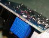
The original video to make the DIY LED floodlight was using an 8Amp DC-DC converter module based on the XL4016 IC. Although the 20 amp module you are using uses different switching components, the voltage (and probably current) control system appears to be the same. The way it works is this: the OUT+ voltage appears on one end of the voltage control pot (it is the left hand end if you place the module upside down with the OUT end nearest to you). The wiper (middle pin) and the right hand pin are connected together and go to the "Feedback" pin of the control system. In the case of the XL4016, "Feedback" is pin 2 and is the negative input of an operational amplifier inside the XL4016. In the case of the 20-amp module, it is a negative input of an operational amplifier that I have not managed to identify yet. In both cases, the positive input of that operational amplifier is maintained at 1.25 volts, probably by a band-gap circuit that produces a stable 1.25 voltage. There will also be a resistor to ground from the "Feedback" pin. In operation, these components form a negative feedback control loop that maintains the Feedback pin at 1.25 volts. Winding the voltage control pot one way to reduce its resistance reduces the output voltage; winding it the other way to increase its resistance increases the output voltage.
External components can be used to feed additional current to the Feedback pin. There are many possibilities. The simplest is to wind the on-board pot up to its maximum and then add an external pot between OUT+ and Feedback. This is quite easy because OUT+ is available as the positive output terminal; and Feedback is both the centre and right hand side pin of that Voltage control pot. By soldering the wire from your external pot to the right hand pin of the on-board pot, you avoid the issue of possibly dislodging the small white component which is between the left and centre pins. It think it is a capacitor, by the way.
I think the on-board pot is 10K. It is a common value and is the value used on the XL4016 module. It is not practical to measure it in-circuit because of the large capacitance in the module across OUT+ to OUT-.
The video instruction for the DIY floodlight recommends using a 22K pot. This will give a new maximum output voltage of about 24.5 Volts instead of 35 Volts. If this is sufficient for your application, that is all you need to do. If not, you will need to use a higher value external pot, or even remove the on-board pot, depending on how high you need the voltage to go.
Further options for controlling the output of this, and other similar, DC converters include feeding additional current to the Feedback pin using the PWM output of a microcontroller (or other PWM source). The PWM signal should be fed through a diode and a resistor of appropriate value, to give the desired range of control.
UPDATE 26 April 2018
After further testing I have concluded that the internal pot on the SZBK07 20 amp module is about 100K (not 10K as it is on the XL4016 module). So to get the same performance from the SZBK07 module your external pot needs to be 220 K. With a 22K pot, the range of adjustment you will get is from a maximum of 6.7 volts down to the feedback pin voltage which is 1.2 Volts. If you use a 220 K pot you will be able to get voltages up to at least 20Volts (my maximum was 21.6 Volts with a 220K resistor).
 . Not a first by any means, as he said it's been that way from the advent of outsourced manufacturing. But, he still hasn't seen the part in person. I have a feeling he will probably make the same suggestion that you are making. The video I referenced, the one that tries to make this a relatively simple experience for us fly by night noobs uses a regulator that didn't have that fuse/capacitor/resistor (?). I had to order something a little higher up the chain, as my sister wanted a panel 4' x 1.5' panel. The specs on the regulator I bought, the one you checked out, could handle the increased amperage - recommended by my father who helped me do the math. The thing is, in this guys video (youtube.com/watch?v=jLia59KfkSw&t=562s) at 8 min 43 sec up - he goes into the use of the voltage regulator (dimmer circuit) & how to wire it. His verbal description only recommends the 2 pins ... even though his own completed version differs slightly from the way he explains how one should go about doing it. He actually captures in his video that his own completed version removed the soldered trimpot from the board, wired it off the board to his 22k potentiometer, and then wired that configuration back to the regulator. Can't tell if he uses all 3. His video tutorial only recommends the previous stated 2 pin aspect. It seems from what you gathered, looking at the pics & the schematics, that doing it that way with the 'hiccup' in play, would result in nothing more than a moderately useless addition to the circuit. So, if I go with the 2 pin method and don't see much change from the added 22k potentiometer, I will def need to go with your recommendation and just use all 3 pins. Unfortunately I will have to try all this out tomorrow and let you guys know how it goes, as I had just this moment to check these very HELPFUL responses, leave a grateful reply - and grab a bite before knocking out another shift
  . Your responses so far have been so much more helpful than anything I was able to find on the subject matter (in a language I could understand ;-)