Continue to Site

Welcome to our site!

Electro Tech is an online community (with over 170,000 members) who enjoy talking about and building electronic circuits, projects and gadgets. To participate you need to register. Registration is free. Click here to register now.

  • Welcome to our site! Electro Tech is an online community (with over 170,000 members) who enjoy talking about and building electronic circuits, projects and gadgets. To participate you need to register. Registration is free. Click here to register now.

Hi vs Low side switching help needed

Status
Not open for further replies.

agent420

New Member
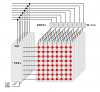
So I'm building one of those 3d led cubes with an 8x8x8 matrix, 512 leds total.

I will be using an Atmel Mega1280 or similar AVR that provides enough io to control 64 individual leds (one plane), so multiplexing will be 64x8.

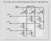
I need to switch power to a load consisting of a 64 leds (one plane), estimated power of 1.3A at 5V. I am trying to avoid the use of dozens of discrete devices, so I'm thinking of using 8 x 2803's to provide individual led control and some power mosfet like the irf510 or similar power transistor to control common rail supply. Can I use these as a high side switch like this? Can I use more common npn in this position, or does hi switching require pnp or pchannel fets?

**broken link removed**


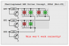
Alternately, if I use low side switching, do you think I can control the common rail by switching the 2803 grounds like this:

**broken link removed**

Thanks for any input you may have.
 
Last edited:
Forgive me but I don't understand why you need to switch power to individual 8x8 LED planes when you can easily turn off all 64 LEDs in a single plane with the microcontroller.

Also, consider using the Micrel MIC5821 or MIC5841 serial-to-parallel sinking driver IC instead of the ULN2803 sinking driver. You'll find you can easily control all eight 8x8 planes at a 12.5% duty cycle with full brightness using a single microcontroller, eight MIC5821 sinking row drivers, and eight IRF520 sourcing column drivers. As a bonus, drive the Output Enable lines on the '5821/'5841 row drivers with a PWM signal at a period equal to the individual column scan rate and you can easily control the brightness level anywhere from full brightness to black.

The example depicted below actually uses the 8 column driver lines temporarily as data lines to load the eight driver shift registers in parallel during a 1% minimum PWM off time during each 1.0-msec column scan period. This drastically reduces the number of microprocessor I/O lines required to drive 512 LEDs.

Good luck with your project.

Happy Holidays. Regards, Mike

concept-clock-8x8-jpg.10475
 

Attachments

  • Concept - Clock 8X8.JPG
    Concept - Clock 8X8.JPG
    141.8 KB · Views: 2,528
Last edited:
You can use an n-channel MOSFET as a high side switch but the gate voltage needs to be higer than the load or supply to the load be the threashold voltage riquired to give the desired current.

For example suppose you require 200mA the supply is 5V and your MOSFET requires 3V on the gate with respect to the source for 200mA. You will require a gate voltage of at least 8V to turn the load fully on, you might be able to use the voltage before the regulator or build a CMOS, or 555 voltage doubler.
 
Mike said:
Forgive me but I don't understand why you need to switch power to individual 8x8 LED planes when you can easily turn off all 64 LEDs in a single plane with the microcontroller.
First off, thank you very much for taking the time to comment illustrate your answer so well - it's much appreciated.

My idea regarding the switching of planes was to accomodate multiplexing by planes of 64 x 8 to keep the duty cycle as high as possible. This way up to 64 led's could be on at a time, so cycle time would be 1-8. I also thought it might minimize driver complexity. Also, I'm not certain if this is an issue, but in order to keep the 3d led matrix assembly as visually minimal as possible, I wanted to address by column and plane... see **broken link removed** as an example of that. I would not have the luxury of electrical connections to every column in 2d arrangement.

I will have to digest your suggestion a bit, specifically as I'm not familiar with the 5841 you suggest, though I do understand your point of shift registers.

Looking at your illustration, does this mean I would need one driver board per plane, requiring 64 pfets? I see your comment says only 8 pfets, but the boards seem to indicate 64.

Edit... nevermind that too, I figured it out. Makes sense now, very clever. ;-)

Thanks again.
 
Last edited:
Hero999 said:
You can use an n-channel MOSFET as a high side switch but the gate voltage needs to be higer than the load or supply to the load be the threashold voltage riquired to give the desired current.

For example suppose you require 200mA the supply is 5V and your MOSFET requires 3V on the gate with respect to the source for 200mA. You will require a gate voltage of at least 8V to turn the load fully on, you might be able to use the voltage before the regulator or build a CMOS, or 555 voltage doubler.
Ok, understood. I guess that introduces some complexity I'd rather avoid. My desire would be to drive the pfet gates directly from the uController io.

I'm still investigating all this, but does the low side arrangement above (via 2803 gnd) hold water?
 
Mike, looked into the 5841... Micrel seems to have dedicated led driver chip, **broken link removed** capable of driving up to 34 leds. Just curious if you have any experience with that chip, and if it might be better suited to this type of project? In theory, that would bring parts count down to 2 x mm5450 + 8 x pfets. However, the 5540's are limited to <15ma per led, I might need the full 20ma mine are rated for (or perhaps a bit more) to get maximum illumination (got a deal on 1000 wide view angle leds for $19).
 
Last edited:
I apologize. The design I suggested does indeed drive a "plane" of 8 columns as you depict. I just wasn't looking at it the right way. The example drawing I provided shows a PFET for each column but it's very simple to implement a single set of 8 PFET drivers for the entire 512 LED matrix.

The 15-ma output limit on the '5540/'5541 would be fine for a non-multiplexed design but you'd need a bunch of them. You need quite a bit more drive capability on a multiplexed display with a 12.5% (1/8th) duty cycle. A peak current of between 80-ma and 160-ma per LED would be required for full brightness.

Addressing by "column and plane" is simple enough in software. Define your matrix array anyway you'd like to make it easy to manipulate in your program and have the interrupt driven multiplexing driver pull data from the array as required to drive your hardware. Interestingly, my PIC driver for that example uses 5x7 character font "column" data for a moving display and I have a small bit of code in the interrupt service routine that formats 8 bytes as "plane" data for loading the 8 driver shift registers in parallel during the next interrupt cycle. The interrupt driver uses about 50.0-usecs every 1.0-msec interrupt (5% of the overall processing time) so there's ample time to manipulate the display data array in the main program.

cube-drawing-png.10476
 

Attachments

  • Cube Drawing.PNG
    Cube Drawing.PNG
    21 KB · Views: 13,485
Last edited:
Not to derail the thread too much, but I was wondering if anybody has seen a matrix display that uses a "charlieplexed" setup? Maxim obviously uses it for the character displays, but it seems like a short intuitive leap to start using it for larger display assemblies.

In the case of volumetric displays, each column would be driven by a 3 wire(=>6 leds) or 4 wire(=>12 LEDs possible) connection. The advantage is that essentially each column uses 3-4 wires that run down the length of the column with no wires going across to other columns. Instead of doing the usual matrix wiring routine, you would end up with each column being an individually wired "spike" sticking out of a main array board.

The tradeoff is that you end up with a lot more pins to drive, *but* the duty cycle is also significantly reduced - a standard $2 16I/O microcontroller would be able to drive 2 full 12LED columns, using only a couple current limiting resistors. The really neat thing would be to then do some brightness compensation on a per-led basis, or just have some real grayscale stuff going on.
 
hjames said:
The tradeoff is that you end up with a lot more pins to drive, *but* the duty cycle is also significantly reduced - a standard $2 16I/O microcontroller would be able to drive 2 full 12LED columns, using only a couple current limiting resistors. The really neat thing would be to then do some brightness compensation on a per-led basis, or just have some real grayscale stuff going on.

The bigger trade off is every pin has to source AND sink current, which basiclaly means you can't use high currents (no drivers).
 
Well, the uC would have two IO lines per "charlieplexed line" - one with a current limiting resistor, the other without. Alternatively a series diode and a resistor would work too, and reduce the number of required IO's to 1 per "charlie-line", allowing the use of external driver chips.

Microcontrollers are getting into the $1-$2 per chip range- an array of 30 of them isn't *that* expensive - and makes for some interesting software.
 
Unfortunately the PIC I/O sink/source current spec' limits the brightness on a charlieplexed matrix. Though you can get very decent brightness with smaller matrices (higher duty cycles).

You also really need to buffer the column driver pins for consistent brightness when lighting more than one LED in any particular matrix column. This then would require six wires running up a six LED cube column instead of three wires.

I suspect the Maxim Charlieplexing driver chip pins can sink/source more current than PIC pins.

Mike

led_bar-dot_prototype-jpg.7001
 
I'm not sure why you say that it would require 6 wires running up? There's nothing except LEDs on the actual column.

In any case: 2x3 array, 3 wires => 1/3 Duty cycle

PIC's look like they have a 25mA limit, AVR's seem to have a 40mA limit, both have a 200mA total chip limit. PICs would be able to drive 8 LED at a time, while AVR's would max out 5 LEDs at the higher current. The emitter follower is pretty much required to source the current.

Average current for both of them would be in the 10mA range - not too impressive, but definitely passable for a desktop plaything.

for a 2x3 array, there is a maximum of 2 LEDs on at a time, the uC would be able to drive 3-4 different charliplexed arrays (CA's), 9-12IO's total.

A 6x6 array of columns would require:
216 LEDs
36/4 = 9 uC's (or 12 uC's if doing 3 columns per)
36*3 = 108 NPN transistors - although the AVR might be able to just drive the LEDs directly if the supply voltage is controlled well enough.

Splitting a large CA acrosss multiple columns doesn't seem to give any wiring advantages when dealing with the LED interconnects - it does seem to decreas the total number of IO's needed though...

Lets say we use the uC to create the biggest array that it can do - a 9x8 array - with a 1/9 duty cycle.
Average current drops ~2mA - barely visible, 72 LEDs per uC. Estimate that we'll need 3-4 uC's, and the question becomes a matter of partitioning... Given 6 LEDs per column, the worst we can do is to have 5 wires (2x3 local array).... Overall, partitioning up a bigger array doesn't seem to give any benefits - and it ends up reverting to the typical array configuration, and making a mess of the wiring.
 
I assumed six wires for a six LED cube column using driver transistors (below). Without them you'd have different brightness levels when lighting one or two LEDs in each Charlieplexed column.
 

Attachments

  • Cube Drawing 2.PNG
    Cube Drawing 2.PNG
    14.3 KB · Views: 545
Last edited:
So say we want to push ~20mA through the LEDs(2V drop), .7V from the emitter follower, and say .5V from beating up the IO lines. 5V - 3.2V = 1.8V, say we want a 100 Ohm resistor. Since this is > .7V, I'd just say connect the resistor between GPx and the emitter follower's output. When the PIC tries to drive the pin high, it'll supply .7/100 = 7mA, with the remainder of the column current going through the NPN, and when the pin goes low, the NPN turns off and we end up with a 100 Ohm current limiting resistor.

In any case, this only would work for the smaller displays. For the larger displays, I'd probably do something like using a 16 channel 80mA constant current driver:

https://focus.ti.com/docs/prod/folders/print/tlc5941.html

And using a pile of schottky diode arrays to source power to multiple arrays from some big mosfets. Just synchronize the column drives - and be sure not to turn on the column that is being sourced and things should be okay.

Using this setup, a tlc5941 would be able to drive 4x 12LED columns at an average 20mA current. The only other parts would be 4 schottky diodes per column. Hmm.
 
hjames said:
So say we want to push ~20mA through the LEDs(2V drop), .7V from the emitter follower, and say .5V from beating up the IO lines. 5V - 3.2V = 1.8V, say we want a 100 Ohm resistor. Since this is > .7V, I'd just say connect the resistor between GPx and the emitter follower's output. When the PIC tries to drive the pin high, it'll supply .7/100 = 7mA, with the remainder of the column current going through the NPN, and when the pin goes low, the NPN turns off and we end up with a 100 Ohm current limiting resistor.
I tried this last year (drawing below) thinking it might be a clever way to drive the 2-pin style Red/Green LEDs. Unfortunately the "folded" matrix provides a forward biased two LED series path for each LED that you want lighted. Bummer!

charlieplexed-experiment-png.10489


For the larger displays, I'd probably do something like using a 16 channel 80mA constant current driver:

https://focus.ti.com/docs/prod/folder...t/tlc5941.html

And using a pile of schottky diode arrays to source power to multiple arrays from some big mosfets. Just synchronize the column drives - and be sure not to turn on the column that is being sourced and things should be okay.

Using this setup, a tlc5941 would be able to drive 4x 12LED columns at an average 20mA current. The only other parts would be 4 schottky diodes per column. Hmm.
Not sure what you're talking about here. Why the Schottky diodes? Perhaps a drawing?

Happy Holidays. Mike
 

Attachments

  • Charlieplexed Experiment.PNG
    Charlieplexed Experiment.PNG
    20.4 KB · Views: 1,413
Now I'm confused - your Nov-05 diagram is just a normal charlieplexed array - with a minor hitch that there are two different forward voltages present - so if the Vf of the red is < 1/2 of the Vf of the green, you'll end up with extra red LEDs whenever you turn on a green one?

In any case, I now remember why I don't like switching schematic drafting programs.. eh, enough grumbling:

I was talking about a configuration for a 4 wire CA, but it's easier to draw a 3 wire one. Current is sourced through pins 1-3 of J5, and sunk through pins 4-9.

Normal diodes could be used, but might as well specify schottky's. Some big mosfets are shared among all the CA's, and the current is sunk with some dedicated LED driver chips.

As for whether wiring up the LEDs in this manner is manufacturable ... dunno.
 

Attachments

  • charliearray.png
    charliearray.png
    5.4 KB · Views: 299
Thanks for all the input, guys :)

I will be using the planar wiring Mike proved earlier using the 5841's to provide sufficient current.

I'm building a monochrome red cube to begin with, both for experimentation and cost. I was able to locate a bulk of 1000 Hi-Efficiency 5mm red leds with a 120' view angle for only $19.99. If this all works out well my plans are to move on to a similar project using bi-color or rgb leds.

The matrix construction will be based on **broken link removed**. However, although they were able to operate the cube, I was not convinced that the 74LS04 hex inverters they used were capable of sourcing 180ma (6 leds @ 30ma ea) reliably, in addition to requiring 64 IO lines to drive them. Curiously, every datasheet and resource I located seemed to indicate that the LS parts would only handle 6-8ma per gate?

I've been doing some coding while waiting on the parts... Looks like I've got some more research to do on FFT algorithms for some of the audio based visualisations I have in mind ;-) Hopefully won't be too bad as I only require 8 bands. Then again, perhaps a programmable filter using a MAX263 or similar, cycling through various bandpass frequencies and measuring the amplitude might accomplish a similar enough effect and save a lot of cpu cycles (and programming headaches!)...

Actually it would be awesome if I could locate a source for this **broken link removed** 8 pin analyzer chip. It just wouldn't get any easier...
 
Last edited:
Status
Not open for further replies.

Latest threads

New Articles From Microcontroller Tips

Back
Top