Continue to Site

Welcome to our site!

Electro Tech is an online community (with over 170,000 members) who enjoy talking about and building electronic circuits, projects and gadgets. To participate you need to register. Registration is free. Click here to register now.

  • Welcome to our site! Electro Tech is an online community (with over 170,000 members) who enjoy talking about and building electronic circuits, projects and gadgets. To participate you need to register. Registration is free. Click here to register now.

Here is full schematic for my power supply, can you check it

Status
Not open for further replies.

Scarr

Member
Hi
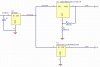
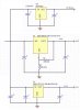
I have attached the full schematic for my 5v,3.8v,3.3v power circuit

Can you check it at see if it all looks OK, I am worried about the dropout between regs after reading a reply to a old post.

Before I comit to buying PCB's etc. I want to know if this circuit is going to work.

Thanks for everyones help :D
 

Attachments

  • power_121.jpg
    power_121.jpg
    80.5 KB · Views: 848
Doesn't look too good... Check the datasheets and do
some math:
http://www.fairchildsemi.com/ds/MC/MC78T05.pdf
**broken link removed**

Biggest problem is the pinouts:
For the 7805 should be:
1 - input
2 - gnd
3 - output

For the LM317 and LM1117 it is "rotated":
1 - adj/gnd
2 - output
3 - input

Next thing is minimum voltage drop should be ca 2.5-3V for all
of the regulators to achive any kind of stability.
For example to get 5V out of MC7805, you must feed it with
at least 7.5V (this is bare minimum!!! better try 8-9V).
Same applies for the other two. If you want 3.8V output,
then 3.8+2.5=6.3V which is again bare minimum (7V is ok).
I suggest rising 5V to 7V by putting three diodes in the GND line
of the 7805 regulator or switching to 7808 regulator.
Either way you will loose 5V output. If you need all three voltages
try powering all regulators from same source instead of cascading
them. If the input voltage is much higher than what you expect
on outputs and current is big, heatsinks are not only required but
maybe not enough. In this case you might want to look for switching
regulators to improve efficiency...
Also make sure that input power is well filtered.
Capacitor of only 0.33uF is not enough if you plan
on using this after bridge rectifier (try 4700uF or more).
 
And one more thing since you are concerned if it will work:
Before you commit to making PCB for this, why not breadboard
everything so you can test it first? It is wise to invest couple of $$$
into something so basic since after you have the power regulated
you will have to build something that will use that power so
you will have to make same decision more than once.
Why not test it on a nice breadboard and only after you are happy with
the prototype go to build the permanent version?
 
Pins not same

Hi,
thanks for your reply, the pin numbers do not corespond to the pins of the IC, these are just a generic schematic symbol, they are correctly connected in real life.

I did have them all coming from a single supply but wanted to drop some components and save some space so I cascaded them.

As for smoothing cap on the input this is what it states on the spec sheet , my project has a DC supply going via a choke and two more caps.

As for prototyping it ver hard to do SMT on breadboard

Thanks
 
And You need decoupling caps for all inputs, outputs about 100n. C1 filter cap about 4700uF.
 

Attachments

  • power_617.jpg
    power_617.jpg
    52.1 KB · Views: 759
Status
Not open for further replies.

Latest threads

New Articles From Microcontroller Tips

Back
Top