Hey all i purchased this on ebay and wanted to verify that i have the pinout's correct before i go and hook it all up to live wires ")
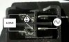
Here is the socket:
**broken link removed**
**broken link removed**
and here is the data on it:
I will be bypassing the fuse since this is being spliced into a surge protector. So that being said i was thinking this is how it would hook up:
**broken link removed**
What i can not figure out (or find a pin out of) is the on/off switch on the top. It has 4 terminals and im not sure which is in and what is out and how the 3 wires hook to it?
Any help would be great!
David
Here is the socket:
**broken link removed**
**broken link removed**
and here is the data on it:
Product Name: Power Socket w Switch Fuse
Material (External): Plastic, Metal
Power Supply: 10A 250V
Plug Type: 3 Pin IEC320 C14
Description:
3 pin IEC320 C14 plug, 7 terminals, is used widely in lab equipment, medical devices, fitness equipment, industrial automation equipment, etc. Use only with a 250V fuse.
I will be bypassing the fuse since this is being spliced into a surge protector. So that being said i was thinking this is how it would hook up:
**broken link removed**
What i can not figure out (or find a pin out of) is the on/off switch on the top. It has 4 terminals and im not sure which is in and what is out and how the 3 wires hook to it?
Any help would be great!
David