Hi,
I hope you are well. I am new to the forum, so I thank you in advance for you help.
I have a tube amplifier from Japan that came with a very strange wiring in a fused power switch IEC 320 C14. I am located in the United States. I have already dealt with the difference in voltage between Japan and the US, but I am having trouble understanding why the power switch came wired in this strange way.
This is the front side of the fused power switch.

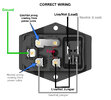
Please find below what I believe is the correct wiring for a fused power switch IEC 320 C14 for the United States.

And, below is the wiring for that power switch in this Japanese amplifier. I have marked some connections with yellow and red, only as reference to the cables coming from inside the amplifier, as I do not know yet which one is neutral and which one is hot.

The fact that the jumpers for hot and neutral coming from the IEC do not go to the same positions (as per the correct wiring) on the switch side would only matter if this switch when OFF only cuts the live/hot wire connection, right? If the power switch actually cuts both, neutral and hot, when OFF then it does not matter where the jumpers go on the right side, as long as both go on the narrow (lower) pair of electrodes, is that correct?
But, why the cable in yellow is connected to the fused hot? sort of bypassing the power switch? I know Japan current is mostly not polarized, but in the United States, what would be the correct way of wiring this for the amplifier?
Any help would be greatly welcome.
Thanks,
Alan
I hope you are well. I am new to the forum, so I thank you in advance for you help.
I have a tube amplifier from Japan that came with a very strange wiring in a fused power switch IEC 320 C14. I am located in the United States. I have already dealt with the difference in voltage between Japan and the US, but I am having trouble understanding why the power switch came wired in this strange way.
This is the front side of the fused power switch.
Please find below what I believe is the correct wiring for a fused power switch IEC 320 C14 for the United States.
And, below is the wiring for that power switch in this Japanese amplifier. I have marked some connections with yellow and red, only as reference to the cables coming from inside the amplifier, as I do not know yet which one is neutral and which one is hot.
The fact that the jumpers for hot and neutral coming from the IEC do not go to the same positions (as per the correct wiring) on the switch side would only matter if this switch when OFF only cuts the live/hot wire connection, right? If the power switch actually cuts both, neutral and hot, when OFF then it does not matter where the jumpers go on the right side, as long as both go on the narrow (lower) pair of electrodes, is that correct?
But, why the cable in yellow is connected to the fused hot? sort of bypassing the power switch? I know Japan current is mostly not polarized, but in the United States, what would be the correct way of wiring this for the amplifier?
Any help would be greatly welcome.
Thanks,
Alan


