Continue to Site

Welcome to our site!

Electro Tech is an online community (with over 170,000 members) who enjoy talking about and building electronic circuits, projects and gadgets. To participate you need to register. Registration is free. Click here to register now.

  • Welcome to our site! Electro Tech is an online community (with over 170,000 members) who enjoy talking about and building electronic circuits, projects and gadgets. To participate you need to register. Registration is free. Click here to register now.

Help with Water Pump

Status
Not open for further replies.
It's looking as though U1a has failed. Can you confirm how pin 1 and U1b output (pins 3,8,9) change (if at all) when the trip test is/isn't pressed for at least 1 sec? And can you confirm the voltages at pins 7 and 14?
 
Pin 1 with trip held down 12.04V. 1-2 sec after trip release, V drops to aboyut 9.7 then steadily drops for a couple minutesto around3.4V.
Pins 3, 8 & 9 are solid 12.05 no matter what.
Pin 7 is 0V.
Pin 14 was wierd. It registered12.04V with pump running. When I pressed trip V dropped to 10.35. When trip wasreleased, V remained at 10.35 for at least a couple minutes.

I'm pretty sure I have an extra 4093 I can install on the piggy back board. If this IC is a goner, I'm thinking I must have cooked it during instalation. Maybe from now on I'll clamp or tape a damp sponge to any IC I solder.
 
Since U1-4 goes low enough to turn on the alarm it almost sounds like R9 might be wrong keeping pin 4 from going to ground.
 
(Pin 1) V drops to aboyut 9.7 then steadily drops for a couple minutesto around3.4V.
Should drop to 0V as soon as Trip is released.
Pins 3, 8 & 9 are solid 12.05 no matter what.
Shouldn't be.
Pin 14 was wierd
Fault.
Since U1-4 goes low enough to turn on the alarm
It doesn't do so consistently, nor does it turn on the alarm fully (hence the grating sound).

All symptoms point to U1 being dead (either from over-cooking or from static damage) :(.
 
Well darn. I'll put my money on cooked. I guess there's a fine line between a good solder joint and a cooked IC. When I get time later this week I'll install a new 4093 on the piggyback board. Seems crazy to get this far and not get it right. Thanks very much for the diagnosis.
 
Another possibility is that pin 14 connection is poor. Try re-flowing connections from pin 14 back to the 12V input before writing the chip off. Also reflow pin 7 connection.
 
I will, thanks.
Hmmm, that makes me wonder if the problem could be where the PS jack plugs into the PDM. I drilled a sloppy hole in the board for that female jack (jackie?) and used super glue to fix it. A little glue flowed into Jackie and if the plug gets the wrong tension, the pump stops. Only when it's under tension. I figured if there's enough current to drive the pump, there's more than enough for the electronics.
 
If the jack ground is suspect and the pin 7 ground is via that point then that could be the problem. The 24V from the PS is not needed just to test U1 trip operation, but U1 does need a solid 12V at pin 14.
 
With a replacement 4093 on the piggyback board, the trip test works as designed. Thanks a billion for getting to the bottom of it! It was well worth the effort. The old IC will R.I.P. where it died.
After the last ground problem with too much voltage at the Vreg, I got strict with the star grounding system. So it was not a grounding problem.

I'll get it put back together, all cleaned up, mounted on the wall and get a pic.
 
Nice to know you've got the PDM working now Joe. Hope the re-assembly goes smoothly. Looking forward to seeing the pic.
 
I missed following this troubleshooting part of the thread. Joe, you have to make one more of each module, so you can use the swap method of repair and still have a system to be able to troubleshoot. Your almost there.
 
KISS, I do have a spare PDM, by far the hardest circuit for me to build.
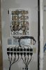
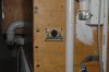
Here's the circuitry and power supplies mounted on the wall in what will be the control room. Just a closet sized room in the basement under the tank. The second pic is the mini board at eye level as you walk into the fish tank room. It's hard to see, but it has a red LED for each filter pump as an alert.

It's not hooked up yet, but I wanted you guys to see the almost final configuration. I made a minor change in the tank/filter plumbing that needs wrapped up before the tank gets refilled.

Thank you guys for helping me put this amazing system together. I really appreciate the nudge you gave me to incorporate the fault sense module, Alec. The FSM is awesome, I love it! When the pumps get fired up, I'll let you guys know how intense the water movement is. Thaks all, from the bottom of my heart, for hanging in there and seeing this through. You are the best!
 

Attachments

  • ptc 2013 004.jpg
    ptc 2013 004.jpg
    2.5 MB · Views: 271
  • ptc 2013 006.jpg
    ptc 2013 006.jpg
    2.6 MB · Views: 269
Nice. A really professional job, Joe. No one would guess this is you first electronics project! I'm sure the tank occupants will appreciate it :).
 
Thanks Alec-that means an awful lot coming from you!
The pumps are hooked up and moving tap water around really well. Every detail is working as planned and everything is staying cool. Wow! What a system!
Thank you guys so much for the guidance and troubleshooting and creative ideas and schematics and for hanging in there. This has been a privilege for me, I can't thank you enough.

I'll let the system run for a couple days before draining the tank. Next up is a geothermal dehumidifier. If it works it will fit nicely into the 'see how few watts can be used to run a large reef tank' theme. I'm about halfway done with the dehumidifier. My fingers are crossed. :)
 
Thanks KISS. I better learn how to do a youtube video.
I guess I spoke too soon that every detail was just right. Two small glitches, either of which I can live with, but who knows maybe there's a real easy solution.

I have 4 new controllers in 'reefcrest' mode running the 4 tide pumps . It ramps the pumps up and down. It's very nice water movement. The alarm beeps about 6-10 seconds into every 30 second cycle. Just a little beep. The pumps do not stop. I switched pumps and new cotrollers around, it made no difference. It also does not matter where the pot on the PDMs are set. If the new controllers are set on high, I don't hear a peep out of it. Worst case I choose between alarm and 'reefcrest' mode.

I mistook the wave timing. With an 8 foot long tank, I felt certain to need several seconds run time for the wave. It looks like the sweet spot is less than the minimum setting. I do have a little wave.

Please don't get me wrong, I am not complaning. I only mention them for the outside chance of an easy fix. As they say, perfect is the enemy of the good. In this case perfect would be the enemy of the outstanding.

You guys deserve all the credit-I just ran the soldering gun. I had a blast-THANKS!!!
 
Can you explain the 'reefcrest mode' Joe? How does the pump speed/switching vary over the 30 sec cycle?
Is the 'little beep' a fraction of a sec or more?
Can you remind us what the normal running current (or wattage) of a new pump is?

To reduce the pump 'on' time, reduce the R1 value in the Wave Controller module (e.g.put another 22k in parallel with it or replace it with ~10k). You could also replace the 500k trimmer with a 50k one if you have a spare.

Edit: There could be a problem if the 'on' time is too short (< ~1 sec). The pump would then hardly get started before it was turned off again. This would mean the average pump current (hence heating) would be increased. The new controller/pump might not like that.
 
Last edited:
alec
Reefcrest must be dealing with a ramped current rather than an initial start-up high current, so maybe the start-up ignore time has to be increased or the current integrated?
I forget how your circuit operates.

I wonder if it woudn't be a bad idea when this thing works to put a suscinct version as an article. I suppose you can't a priori edit the contents of an article.
Just a thought.
 
@KISS
maybe the start-up ignore time has to be increased or the current integrated?
Joe has already tried the PDM trimmer at max and I guarantee he won't be keen on modding the PDMs further :D, so I'll look into slugging the beeper drive circuit instead.

joe
Edit: Ok. I think what is happening in the reefcrest mode is that the short-term-average pump current is being ramped as KISS suggested. This means the FSM interprets the initial part of the ramp as loss of current = fault and triggers the beeper. Joe, I suggest you try putting another 100 Ohm resistor in parallel with the existing R2 (100 Ohm) in the FSM dedicated to the tidal system. This will reduce the current trip threshold of the FSM, hopefully enough to overcome the spurious beep problem.
 
Last edited:
I'll start with the wave timer. I don't have a fine adjustment type 50K pot so I'll reduce R1. I appreciate the heads up about turning the pump on and off real fast. The new controllers turn the pumps on and off faster than I'll need to, so I think we'll be OK there.

Haha, you are so right about me not wanting to mess with the PDMs. Those gave me all kinds of grief.
Thanks for those fixes.

BTW, the sticker on the back of new pumps say 40W.
 
Status
Not open for further replies.

Latest threads

New Articles From Microcontroller Tips

Back
Top