Continue to Site

Welcome to our site!

Electro Tech is an online community (with over 170,000 members) who enjoy talking about and building electronic circuits, projects and gadgets. To participate you need to register. Registration is free. Click here to register now.

  • Welcome to our site! Electro Tech is an online community (with over 170,000 members) who enjoy talking about and building electronic circuits, projects and gadgets. To participate you need to register. Registration is free. Click here to register now.

Help with Water Pump

Status
Not open for further replies.
Glad to hear the grounding is sorted.
The flick is a bit much with 390K at R3 and 0.1uf at C10.
I'm surprised. Trimmer(max) + 150k = 650k, which wasn't enough. Trimmer(min) + 390k = 390k, which is now too much?:confused: Did you remember to crank the trimmer back towards its 'other end'?
 
I think the flick fussyness is because I probably did not have the new controller on the setting that will be used in the tank.

Would it make sense to replace R3 with a trimmer for gross adustment and use the 500K trimmer for fine adjustment? (the 500K trimmer has 15-20 turns from one end to the other)

I am thrilled to have the tidal system working. It's nice to be down to teeny details like dialing in a flick. A flick that happens right on time, every time. ha ha! :)

Thanks for helping me get this squared away, you guys.
 
Last edited:
Would it make sense to replace R3 with a trimmer for gross adustment
Not to me. One trimmer should give all the adjustment you need, in conjunction with a fixed resistor for the gross setting. Ideally you would have a good idea of what the total resistance should be and the fixed resistor would account for some 90% of that value. For historical reasons we're not in that situation.
I'm still puzzled as to why, when the 150k + trim (i.e. 650k) gave you nearly enough flick time, replacing 150k with 390k would have given you too much time. Granted, 890k total may be too much; but you can trim down to 390k total. I would have expected a bit past mid-point on the trimmer (~ 750k total) to be somewhere near right? BTW, on some trimmers the wiper can be adjusted past the intended end points and is then open-circuit, giving weird results.
 
I've got the tidal system set aside while I modify the 8 cords to the new PSs for fuse and ground. I had a hard time cutting into these brand new shiny cords. I don't know why, I just did. After I cut the first one, it wasn't so bad.
IDK, but I doubt water resistance would have much impact on a flick. At least from a visual standpoint. I am looking staight down into a bucket of water with the pump pointing up.

This trimmer will spin forever, but makes tiny clicks when it's at one end or another. I turned it until it clicked and looked at the flick. I'll try this setup again, but this time I'll turn the trimmer back 1/2 turn from max and 1/2 turn from min.

BTW, the 0.15 caps arrived. They are non-polar. IDK if they could possibly be useful at C10 to help dial in the flick. At this point C10, 0.1uf, is dangling from the board in a temp hookup.
 
IDK if they could possibly be useful at C10 to help dial in the flick.
Suck it and see :)
 
I wired two circuits from my breaker box into the fish control room. I plan to put half the pumps on each circuit. Each pump will be on an independant GFI.
Is a conflict likely when the 24V line from every new PS is fed into the beefy diode backup for TPASM 24V? The ground from thes two mains circuits will also be combined.

I finished the final touch up soldering and scrubbed the back of every board with a toohbrush and dishwashing soap. As soon as everything is mounted, I'll post a pic.

You guys have been unbelievably helpful-thank you so much.
 
Is a conflict likely when the 24V line from every new PS is fed into the beefy diode backup for TPASM 24V?
A well-raised point, but there shouldn't be a conflict as the diodes provide DC isolation. Although each new PS is nominally 24V, in practice they may well be slightly different and the one with the greater voltage will be doing most of the work (little as it is) in powering the 12V regulator.
Awaiting the pic :cool:
 
That's a load off, hurray!
BTW, the flick is exactly what I was looking for. 1/2 turn of the prop. Hopefully enough to prevent fish from making the inside of the pump a bedroom without bruising them up.
 
Joe:

The GFCI should only be required for the AC to DC power sources. i.e. The big switching power supplies if I have everything straight. Which basically means two GFCI's.

Also, if you look around, you can find GFCI's with Fault indicator lights. On when tripped.
 
BTW, the flick is exactly what I was looking for. 1/2 turn of the prop.
Good. What values for C10/R3 did you end up with?
 
Kiss, I did not want one tripped GFI to take down half the tank, so I wired a bunch of GFI receptacles in paralell. Each pump's PS will have a dedicated and independant GFI. Safety AND redundancy. BTW, the FSM circuit will alert me to a pump without power. Nice. :)

Alec, 0.1uf at C10 and 390k at R3. A thing of beauty.

Thanks you guys. I wish this weekend belonged to me, but my brother is visting soon and Leah thinks the house is a mess. Looks fine to me......I'll nickel and dime this home stretch.
 
I realize that, but I though you really only would have two 24 VDC ~6A supplies.

Well 20% of the project usually takes 80% of the time, so good luck.
 
Thanks KISS. Every new pump has its own seperate PS, so I put every PS on its own GFI. Eight new pumps for water movement and two old pumps for filtration.
 
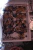
Got this thing all wired up and all systems are go! Flick, wave, tide, battery backup, charging system and fan, fault sense module. It seemed easier to hook up with the circuit boards fixed in place. It's still kinda messy because the pump leads are in a temp hook up and the dangling little board will end up in the fishroom and the fan will need to have its' leads lengthened and fastened to blow on the LM317.
One small glitch on one of the tidal PDMs. When the trip is pushed for the alarm, the pump and pump LED turn off and the alarm sounds. The red red warning LED lights up, but as soon as the alarm button is released the pump LED and pump go back on. Meanwhile, the alarm and red LED stay on for the normal 30 seconds or so. The Pizo has a broken chattering sound on this PDM. The pump toggleslike it's supposed to so I don't know if taking the PDM apart at this point is worth the risk. I checked the ground and it looks good. Speaking of ground, thank you Alec for the grounding diagrams. They were absolutely invaluable. This entire system is a masterpiece. I can't thank you enough. Also, thank you KISS for hanging in there with us. Your troubleshooting skills and insights were a tremendous help. RonV and anyone else who contributed, thank you one and all.

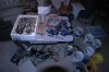
Once this is mounted to the wall, I'll get a final pic posted. I can hardly wait to see how the system moves the water.
 

Attachments

  • manaway 2013 594.jpg
    manaway 2013 594.jpg
    2.7 MB · Views: 247
  • manaway 2013 591.jpg
    manaway 2013 591.jpg
    2.9 MB · Views: 270
Good work, Joe! Be sure to have a backup of all the schematics and of this lengthy thread!
but as soon as the alarm button is released the pump LED and pump go back on.
Check D4 in the PDM, and the connections from U1a output to D4/D10.
 
Thanks you guys!
D4 and D10 both look good. The cathodes of D4/D10 are connected to pins 2 and 4 of U1a, and I could not find any debris or anything, so IDK what the deal is with that PDM. I'm prettyy sure that PDM tested good before I set it aside, is it possible that a glitch in the FSM or something else is to blame? Could a tiny bit of water be stuck inside the IC, from when I washed them? I can live with one pump not being protected, just wondering.

Alec, you are a creative artist, you do amazing work. You guys are the best! Thanks!!!
 
Last edited:
Status
Not open for further replies.

Latest threads

New Articles From Microcontroller Tips

Back
Top