Continue to Site

Welcome to our site!

Electro Tech is an online community (with over 170,000 members) who enjoy talking about and building electronic circuits, projects and gadgets. To participate you need to register. Registration is free. Click here to register now.

  • Welcome to our site! Electro Tech is an online community (with over 170,000 members) who enjoy talking about and building electronic circuits, projects and gadgets. To participate you need to register. Registration is free. Click here to register now.

help with some parts on a circuit board

Status
Not open for further replies.

corvairbob

New Member
i have a traffic light controller that is a small circuit board maybe 4x4" anyway i was messing around trying to get the controller to work a cross walk light as well anyway i managed to mess one of the light circuits up. so now the yellow light stays on while the green and red keep cycling.

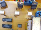
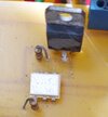
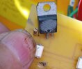
so i can't get parts because the builder scratched the numbers off the parts, my guess was to keep other from building there own. so here are a few photos so someone may be able help me identify them. the output is a t0-220 case device and it has along the bottom on either side of a dot that i think indicates the gate or the collector, it has c3 44 that is all i can get from these and that device has 120vac on both outer pins and the center pin goes to the light and also connects to a resistor and then to a ic module that i think may be a triac anyway when the center pin gets 120vac on it the bulb lights up.

that same center pin also goes to that is module that has an f in the upper right corner it is 6 pins and has a resistor between that module and the output device.

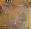
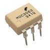
first is the back i put the wire on it to repair the burnt traces the left one is the yellow and that is on all the time if you look at the2nd photo the left and right pins are 120vac all the time and the center one gets 120vac from the white device just below it. based on the f on my is i think it is the last photo a triac. this one is used to power lights and such, but i do not know if the to-220 is a power transistor or a triac. so maybe someone can help me id these 2 devices based on the back side traces.
thanks
 

Attachments

  • IMG_20220615_084615.jpg
    IMG_20220615_084615.jpg
    864 KB · Views: 205
  • IMG_20220615_084626.jpg
    IMG_20220615_084626.jpg
    950 KB · Views: 208
  • IMG_20220615_084626-1.jpg
    IMG_20220615_084626-1.jpg
    206.2 KB · Views: 199
  • IMG_20220615_084642.jpg
    IMG_20220615_084642.jpg
    480.5 KB · Views: 213
  • moc3063-zero-cross-triac-optoisolator-ic-800x800.jpg
    moc3063-zero-cross-triac-optoisolator-ic-800x800.jpg
    60.7 KB · Views: 215
well i'm glad you got your supply but for me i need only a few and i found them on ebay and they say shipped with a 2 week delivery. and as you say they may get here on time and then maybe not. but one seller sent me a note saying not until sept and they show next week in there delivery time frame. so if it fails in that window i will give them neg feedback based on the false delivery date. they should have changed that date then as most other have done already.
thanks.

Yes, keep an eye on it.

In the meantime you could confirm if you even need them? - if a lamp won't light, then putting a short across pins 4 and 6 of the opto, should turn the TRIAC on. If the light is permanently lit, then removing the opto should make it go off.

Anything other than those two results means the triac is faulty - which as I said is a far more likely scenario than the opto.
 
the light stays on i measured voltage at all the pins on the triac and i have 120vac at all 3 triac pins so either the moc3063 is bad or the triac is bad and is applying 120 vac to the gate on the triac. that is why i got both parts. i will just replace both of them and see it it starts to cycle. if not then i will toss it out and get a new one. i could gat a new one now but i want to see if i can fix the old one just because.
thanks.
Like I said, take the opto out, and see if the light still stays on - if it does the triac is faulty - I wouldn't even think of considering the opto-coupler, they are incredibly reliable. I've repaired hundreds of light units etc. over the decades, and it's pretty well always the triacs - as I said previously, even a bulb failure commonly takes the triac out.

For that matter, as you have two working channels, swap the triacs between one of the good channels and the bad one - but a simple ohms test round the faulty triac should show it's short, compare it to the other two.

For a simple 'comparison', you have a flat tyre on your car - is it the tyre?, or is it the brake disc? - tough decision.
 
ok i went and cut the resistor that goes to the gate on the traic and yes the light stays on so it must not be the opto isolator that failed but the triac as one said may be the defective device. so that is why i have 120vac on all 3 pins so i have both parts in the mail and will install the traic first as i said and it looks like that will be the faulty part and the board will then work again. i will put the opto isolators in the electronics parts bin for some future repairs if needed.

what i was going for is the walk light would go on with the green and then when the yellow and red lights turned on the don't walk would come on. but i have to block the red light on the signal when the yellow light is on and making the don't walk light turn on. so i tried a bridge rectifier and that failed and caused this issue.

red on O = don't walk O
yellow on O = don't walk O
green on O = === walk O

what i tried to do was put a diode in to keep the red light off during the yellow light so the don't walk would turn on and then when the re light cam on i also got the yellow light so i was experimenting. i guess i either get the board that is built for this and be done with it. so if this board fails again i will get the correct board and be done with-it, but for now i have parts in the mail and will repair this board and keep using it as is.

thanks
 
Last edited:
Cutting the resistor would be one way, but why not just unsolder one end?.

But first measure the triacs on ohms, across the two anodes on each triac. No need to disconnect anything.

Simple way - hold one meter probe on the metal tab, and apply the other probe to the centre pin - if this reads short?, then it's a non-isolated triac, so you can continue. So meter probe on tab, then touch the other probe to the outside two pins in turn - repeat this across all three triacs - they should all read pretty well the same (high, or O/C). If the triac is faulty, it will most likely read low on this test.
cutting the resistor at this time is the fastest and easiest way to test that out. i did it and it worked. i tested the triac and all 3 pins had 120vac on them so i did not know at that time if it was the triac that shorted or maybe the opto that shorted and was turning on the triac. but by just cutting the resistor out of the circuit as a test proved it was the triac. i can re-solder it when i get the new parts. it is fast and easy way to test and saved time taking the board out of the signal and then putting it back in.
thanks.
 
ok i got the parts installed the parts and connected test bulbs up to the board that bulb came on dim and the resistor started to glow. so i took it apart and tossed it in the trash. i can get a new board for 30$ and i have 15$ into parts now. but it was worth a try. thanks guys for the help it was a crap shoot at best without having any real number to go with.
 
Status
Not open for further replies.

Latest threads

New Articles From Microcontroller Tips

Back
Top