Continue to Site

Welcome to our site!

Electro Tech is an online community (with over 170,000 members) who enjoy talking about and building electronic circuits, projects and gadgets. To participate you need to register. Registration is free. Click here to register now.

  • Welcome to our site! Electro Tech is an online community (with over 170,000 members) who enjoy talking about and building electronic circuits, projects and gadgets. To participate you need to register. Registration is free. Click here to register now.

help with some parts on a circuit board

Status
Not open for further replies.

corvairbob

New Member
i have a traffic light controller that is a small circuit board maybe 4x4" anyway i was messing around trying to get the controller to work a cross walk light as well anyway i managed to mess one of the light circuits up. so now the yellow light stays on while the green and red keep cycling.

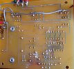
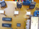
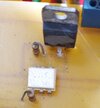
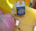
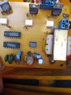
so i can't get parts because the builder scratched the numbers off the parts, my guess was to keep other from building there own. so here are a few photos so someone may be able help me identify them. the output is a t0-220 case device and it has along the bottom on either side of a dot that i think indicates the gate or the collector, it has c3 44 that is all i can get from these and that device has 120vac on both outer pins and the center pin goes to the light and also connects to a resistor and then to a ic module that i think may be a triac anyway when the center pin gets 120vac on it the bulb lights up.

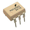
that same center pin also goes to that is module that has an f in the upper right corner it is 6 pins and has a resistor between that module and the output device.

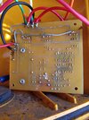
first is the back i put the wire on it to repair the burnt traces the left one is the yellow and that is on all the time if you look at the2nd photo the left and right pins are 120vac all the time and the center one gets 120vac from the white device just below it. based on the f on my is i think it is the last photo a triac. this one is used to power lights and such, but i do not know if the to-220 is a power transistor or a triac. so maybe someone can help me id these 2 devices based on the back side traces.
thanks
 

Attachments

  • IMG_20220615_084615.jpg
    IMG_20220615_084615.jpg
    864 KB · Views: 205
  • IMG_20220615_084626.jpg
    IMG_20220615_084626.jpg
    950 KB · Views: 208
  • IMG_20220615_084626-1.jpg
    IMG_20220615_084626-1.jpg
    206.2 KB · Views: 199
  • IMG_20220615_084642.jpg
    IMG_20220615_084642.jpg
    480.5 KB · Views: 214
  • moc3063-zero-cross-triac-optoisolator-ic-800x800.jpg
    moc3063-zero-cross-triac-optoisolator-ic-800x800.jpg
    60.7 KB · Views: 215
1. Do you know if any of the chips is a microcontroller?

2. How is the board supposed to function? What is the light/timing pattern?

3. Are there any input that can change the light pattern, as from a vehicle detector of pedestrian crosswalk button?

4. Photo showing the entire top side of the board

5. Indicate on the photo, or in a separate sketch, the various in and out wires and their functions.

ak
 
They will be zero voltage switching opto-triacs, similar to the one you linked - and triacs such as BTA08 series for the actual output power control.

It's a common type of circuit.
 
ok so your saying the white ic is a bta08 type triac? i'm thinking because the light is just staying on that the output to-220 device may still be good based on the fact that on the other 2 devices if the center pin is energized with 120vac those lights do turn on. so i think the actual defective device is thee white device.

so i think what your telling me is i need to find a triac with a zero voltage for the switching? i guess i can get that info from the websites i got those photos from, providing your talking about the white device
thanks
 
1. Do you know if any of the chips is a microcontroller?

2. How is the board supposed to function? What is the light/timing pattern?

3. Are there any input that can change the light pattern, as from a vehicle detector of pedestrian crosswalk button?

4. Photo showing the entire top side of the board

5. Indicate on the photo, or in a separate sketch, the various in and out wires and their functions.

ak
have no idea if any are mini controllers at the are i think is defective

the board times the traffic signal to go green yellow and red in a repeat pattern

the timing can be changed with a mini pot

i did post that but is you want to actually see the edges i can get that

i will try to get a diagram but if you look close at the back and the turn it over it is easy to see? but let me see what i can draw up.

this is the best i have at this time only the far left is not there and that is just the board
the back side you see wires that is to repair the burnt traces you can see the burnt ones
thanks
 

Attachments

  • IMG_20220615_084626.jpg
    IMG_20220615_084626.jpg
    1.1 MB · Views: 187
  • IMG_20220615_084615.jpg
    IMG_20220615_084615.jpg
    1.4 MB · Views: 184
Last edited:
The lower left 8-pin DIP probably is a 555. Can you read anything on the face of the TO-92 part? It is in the right place to be a low power linear regulator.

Is this a commercial unit? Both the design technique and the layout are very poor. OTOH, the transformer is riveted to the board, something you don't see in hobbyist assemblies.

And, that is a very large transformer for such a small circuit. Is board flexing a problem?

ak
 
Left hand pic in post 6:

Bottom 8 pin ic left of the trim pot is a 555.

Immediately above the trim pot, the 4 pin ic is a 1A bridge rectifier.

The 2 ic's to the left of the bridge rectifier will be standard cmos ic's, possibly shift registers (I need to chase down the schematic to confirm which ones when I can find it - busy today so might be a day or so).

The 3 white ic's are opto-couplers similar to what OP has posted and hopefully zero crossing.

The 3 TO-220 devices are Triacs probably in the range of 6 -10 amp rating 400V or more.

Is this a broken connection?

IMG_20220615_084615.jpg
 
i do not know? i did notice that but i think if it was a broken trace, that light would not be on as if you look at the same circuit to the right you will notice the trace is connected and in that part of the circuit on the reverse side there is a resistor making that circuit from the white ic device your calling opto-couplers. and i think if that trace was broken the light just would not tune on. that trace goes to a resistor and the resistor drops down to the coupler. i think i have a line on these on ebay but i will do some more research to make sure i get the correct voltages. i wonder if the amp rating on these are that high being they control a 60 watt bulb at the most. that is what this came with when i got it and i asked the traffic control people and they said they put 60w bulbs in then at 130 volts to make them a bit dimmer but to also make them last longer.

also at that point on the board the other 2 lights at that point do not have power when they are off, this one that you have circled at that point i have 120vac and also if i measure back to the next solder point i have the same 120vac and at that point is the resistor.

thanks
 
ok so your saying the white ic is a bta08 type triac?
No, the white six pin devices are the opto triacs which are "triac drivers", just to control the gate on a higher power triac.
The MOC3063 such as in your photo is a opto triac.


The upright TO-220 devices will be the BTA08-400 series (or similar) power triacs.

Together they form some variation of a circuit such as this, though driver from an IC rather than a transistor.
The MOC3021 is another of many triac drivers, so that, a limiting resistor and a triac allow isolated 120 / 24V power control from a low voltage control signal.

triac-driver-gif.113705
 
1. Do you know if any of the chips is a microcontroller?

2. How is the board supposed to function? What is the light/timing pattern?

3. Are there any input that can change the light pattern, as from a vehicle detector of pedestrian crosswalk button?

4. Photo showing the entire top side of the board

5. Indicate on the photo, or in a separate sketch, the various in and out wires and their functions.

ak
Looking at how old (and crappy) the board is, it's unlikely to use a micro-controller, and nothing in the pictures seems to suggest that it might (from that long ago it would most likely have an external clock crystal).
 
No, the white six pin devices are the opto triacs which are "triac drivers", just to control the gate on a higher power triac.
The MOC3063 such as in your photo is a opto triac.


The upright TO-220 devices will be the BTA08-400 series (or similar) power triacs.

Together they form some variation of a circuit such as this, though driver from an IC rather than a transistor.
The MOC3021 is another of many triac drivers, so that, a limiting resistor and a triac allow isolated 120 / 24V power control from a low voltage control signal.

triac-driver-gif.113705


ok thanks very much. i wll try getting a moc3021 being i'm controlling 120vac and also a to-220 triac that is the bta08-400 type and give them a try out to see if that fixes the flash. i'm leaning on the opto triac as teh issue being i nowhave the 120vac on the gate of the to0220 triac. so the moc3012 unit must have failed and it sending the trigger votlage to the to-220 triac to keep that device turned on the worse is it will not work and or burn out the new parts.

ok i will get one of these and give it a go, but i will not install this at first as like i say i think this is good if it fail i will install one, but i will ahve both of them just in case. and i will set up a test bench to test the repair on the bench before i reinstall it. it will be easier.

thanks
1655466287495.png


thanks
 
The 3021 is a "Random phase" type rather than zero crossing - it will likely cause radio / TV interference in your application, as the light can switch at any part of the AC cycle - and your board has no suppression or filtering to handle that.

Use a zero crossing / zero voltage switching one such as the 3063 you show in the original post.
 
thanks i have on ordered now. this light is out on the front of the garage and not by any radios and tv's so it may cause interference but i'm guessing it will me minimal at best and not bother anything in the house. or should i will get the one of the moc 3052 or a moc 3063 device and see if that works better.

i got the moc3021 based on the numbers you showed in your diagram so do you think i need to forgo the moc3021 in favor of the moc3052 or the moc 3063? i can order one of those and return the one ordered.

because this is a rather cheap signal module my guess is the builder used the cheap components.

thanks
 
Last edited:
thanks i have on ordered now. this light is out on the front of the garage and not by any radios and tv's so it may cause interference but i'm guessing it will me minimal at best and not bother anything in the house. or should i will get the one of the moc 3052 or a moc 3063 device and see if that works better.

i got the moc3021 based on the numbers you showed in your diagram so do you think i need to forgo the moc3021 in favor of the moc3052 or the moc 3063? i can order one of those and return the one ordered.

because this is a rather cheap signal module my guess is the builder used the cheap components.

thanks
If you have a garage door opener, it has a radio receiver.
 
my garage door opener is on a different type of system it is digital but we will see, i have both the triac and the opto isolators in the mail some are saying the triac may have been what failed so i guess that is the easiest part to change out so if that failed and that is why i see 120vac on all 3 pins of the triac then replacing the triac should fix it if that fails them the module will be next. at this time is is operating, so when the parts get to me i will set up a 3 light test station and then replace the triac and if that fails i will replace the module. thanks
 
Last edited:
ok just for the heck of it i orderd some 3063 opto isolators. and will just use that number being they were cheap. and the seller of the first one the moc3021 units sent me a note telling me i will not see them until aug or sept. and the guy for the moc3063 tole me in a few weeks. so that may be a stock issue. then i will see how it goes. being i have both parts in the mail i will just change them both out because i will have it on the bench for repair at that time.
when i get it done i will let you know how it went. it will be a few weeks out not waiting on parts. thanks

Many parts are hard to find these days, with even many common parts been on back order, or not even available to put on back order.

I was wanting 2N7000 FET's at work the other day, and while various 'types' at RS Components were out of stock, with either long delivery dates, or no date at all, I was able to find 800 in stock, 600 in the UK and 200 in Europe, so I ordered 1000 (to get the 1000 price break), 600 came next day, 200 a day or two later, and the other 200 are on (whenever) back order.

I will warn you, don't expect any 'expected delivery dates' to be in any way accurate - we used to order a specific cable from RS, and it was very often on back-order - and from the small quantities they ever had in stock, I suspect we were pretty well the only people ordering it. Anyway, we back ordered some, with a delivery date for about a month ahead, but it never arrived - and when I checked the status on-line, the date was a month further ahead - I just thought 'idiot, you read the date wrong when you originally ordered', and waited another month.

Another month passed by, still no cable, so checked again - and the date had moved a further month forward - at this point I realised I hadn't made a mistake originally.

So I rang them, to be told the 'anticipated delivery dates' were mostly guesses, and that he 'hoped' the cable would arrive before the next estimated date.

To make matters worse, they have now stopped stocking the cable entirely!!!.

As a result we're now buying 'similar' cable from Farnell, which because it's American cable comes in feet not metres.

Interestingly, and something others might find worth checking (because it sounds so stupid), it's a fair amount cheaper (like £20 or so) to buy ten 100 foot reels, rather than one 1000 foot reel - how's that work out then?. However, 100 foot reels do look puny :D - but as we almost entirely use it in just over 1 metre lengths, the smaller reels are fine.
 
well i'm glad you got your supply but for me i need only a few and i found them on ebay and they say shipped with a 2 week delivery. and as you say they may get here on time and then maybe not. but one seller sent me a note saying not until sept and they show next week in there delivery time frame. so if it fails in that window i will give them neg feedback based on the false delivery date. they should have changed that date then as most other have done already.
thanks.
 
Status
Not open for further replies.

Latest threads

New Articles From Microcontroller Tips

Back
Top