Continue to Site

Welcome to our site!

Electro Tech is an online community (with over 170,000 members) who enjoy talking about and building electronic circuits, projects and gadgets. To participate you need to register. Registration is free. Click here to register now.

  • Welcome to our site! Electro Tech is an online community (with over 170,000 members) who enjoy talking about and building electronic circuits, projects and gadgets. To participate you need to register. Registration is free. Click here to register now.

Help with Reverse Engineering Li-Ion laptop battery BTY-M6D

Status
Not open for further replies.

P.Vlad

New Member
Hi guys,
I'm quite the newb when it comes to electronic circuits therefore I need your help with this. (also after some pondering I figured this is the right thread to post instead of "repairs")

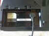
Background: Laptop power jack is wrecked went to the repair shop, they tried to replace it but failed, the motherboard got/was damaged. (pretty common failure to laptops due to greedy companies soldering the jack directly to the motherboard with no additional support).

The laptop can still run on the battery as it is a separate circuit. Therefore I would like to hook up a DC power supply to the battery. This gets complicated because of the additional data exchange between the battery and the laptop.

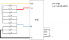
So I am trying to remove the Li-Ion cells from the battery and connect a power supply. I can only draw the visible part of the battery setup, and I can only guess the output of a single cell, but most likely your guesses are better:

https://drive.google.com/folderview?id=0B-0UNw6xiR-aWHpJUjlkMzZOWEE&usp=sharing (for pictures, could not upload on the forum :O kept getting errors)

upload_2016-2-28_20-15-37.png


Here are the questions:
- What does MV and JV stand for ? this might help figure out what the PCB does with this inputs (note that blue one is actually white, and this 2 wires are also physically thinner then the black and red).
- How could I replace the Li-Ion cells with a DC power supply (or two) and trick the PCB into thinking it always has 100% full battery, and what would be the required stats of the DC power supply?
- Would it be possible to use the original laptop power supply, It is a 19V 9.5A 180Wh monster while the battery overall output is 86,6Wh ? (Like having a mega battery)

Any thoughts are much appreciated,
Thanks.

*Fixed the diagram.
 

Attachments

  • upload_2016-2-28_17-16-40.png
    upload_2016-2-28_17-16-40.png
    11.1 KB · Views: 428
Last edited:
Welcome to ETO!
MV and JV are nodes which the charge/discharge ciruit monitors to ensure that over-charge and over-discharge don't occur and cause a fire risk.
BTW the centre 3 cells are shown with reversed polarity.
 
Welcome to ETO, P.Vlad!

MV and JV leads may also be involved in "balancing" the recharge of the battery sets.

Read this thread and see if anything clicks with respect to your situation.
https://www.electro-tech-online.com/threads/power-laptop-with-ac-adapter-through-battery-port.89885/

As you can see, in some cases, the Brand of a laptop has a bearing on your question (some laptops look for a very specific battery ID before they will operate correctly).

Get back to us if you're still unsure.
 
Hi All, thnx for the replies,
maybe I can rephrase,

what would be the voltage on JV and MV when the battery is full?
or is it that only the potential difference between JV and MV matters?
 
A normal Lithium cell is 4.20V when it has at a full charge. It is not "full" of anything.
Therefore if -V is 0V then JV is +4.2V, MV is 8.4V and +V is 126v when the battery has a full charge.
 
Hi Alec, I disagree with you on the centre three cells being reversed.
Post #1 has since been edited. The original circuit (to which I was referring) is in the post #1 attachment.
 
Hi Alec,
I didn't think you would get something like that wrong. I must have looked at the picture before its was corrected. I have also noticed that I must of missed the comment in post #1 "*Fixed the diagram" Sorry about that.

Les.
 
My feeling is this is beyond the ability of the OP as he could not even work out the voltages on the tapping on the battery that are used to monitor individual cell voltages.

Les.
 
Sorry to dig this up, but I have the exact same battery with the exact same problem. Had the same thought about fixing, hence ending up here.

Curious if a solution was ever found, though I doubt it looking the the OP post count.
 
I would suggest three separate, isolated, Li-Ion chargers, one across each parallel group of cells.

True, maybe just keep the cells topped up with an external charging circuit. Actually, am I overthinking the smart battery setup? Can I just ditch the Li cells and supply 4V with dummy cells...or will the SMBus sense that something is amiss?
 
Hi fishkur, same battery, same problem here. Did you find a solution?

I got busy and shelved this for a while but did try a couple things.

Like Vlad, I wanted to ditch the cells completely to eliminate hassles of overcharging, etc. I think it could be done but I'd probably recommend Diver's solution above (3 isolated chargers to handle each set of cells independently). This should satisfy safe charging though I'm not sure about the cell balancing. I see this as a way to extend the life a bit, not really a forever fix so my gut says each group of cells will be "close enough" to not bother with balancing.

Here's what I tried:
I ended up putting a DC/DC buck converter between the battery and a 12VDC power supply. I actually piggybacked some wires between the battery socket and the laptop pins just as a temporary test (before I got serious and started drilling holes in the laptop lol). This satisfied the clock/data/presence pins as they all remain intact and functional on the battery circuit board.


This is a video that put me on this direction:

The idea is that we need to control the current going into the battery but we are putting it in before the BMS (battery management system) within the battery itself. It will take care of load balancing, etc.
The buck converter pushes constant current (which you set) until the battery reaches a certain level of charge, then switches to constant voltage to maintain. You'll have to set the voltage to the pack (11.1V) and the current to whatever you desire. I'd recommend a low current which will take longer to charge but not stress anything since this is probably a bit risky.

I didn't get around to doing a battery calibration to figure out proper runtimes so my reported charge % and runtime would be all over the map. I did try running the laptop while charging and it worked fine, but wanted to do some testing with it under a full load and see if it would support this. Nothing got hot during the time I did run it...so potential win?

Ultimately, I accidentally yanked a wire out of the buck converter and caused a short circuit and blew up the IC...that happened this morning and I only stumbled on this because I'm retracing my steps to find the part that I ordered lol.

I will check back for the next couple weeks or so - if you (or anyone else) have any questions or comments I'd love to discuss.
 
Thank you, fishkur. I will certainly try this out sometime, when i have more free time on my hands.
 
The simple solution to a three or four cell balance charge is - a balance charger.

They are readily available for charging lithium packs for RC models.
eg. **broken link removed**

I've got a couple of those exact ones, I run them from 12V "brick" style PSUs I have about (laptop style blocks).
(Search ebay regularly - mine cost me £12.50 each).

You need to buy the balance cable and wire that to whatever cell pack you are using, plus the two pin power connector or adapter cable with one of those, but then you just set the cell type and number, plus max charge current on the charger and it handles everything.

I have multiple cells and various packs made up for a number of gadgets and these work fine!
 
No, not the external pins - it would need wiring directly to the cells, if the battery casing was open.

Some of the earlier posts related to working on or changing cells, I did not know if yours did or not.
 
No, not the external pins - it would need wiring directly to the cells, if the battery casing was open.

Some of the earlier posts related to working on or changing cells, I did not know if yours did or not.


This will absolutely work. In fact, the battery pack itself has a balance charger built into it so I was taking advantage of that without the hassle of opening the pack itself.
 
Last edited:
Status
Not open for further replies.

Latest threads

New Articles From Microcontroller Tips

Back
Top