Continue to Site

Welcome to our site!

Electro Tech is an online community (with over 170,000 members) who enjoy talking about and building electronic circuits, projects and gadgets. To participate you need to register. Registration is free. Click here to register now.

  • Welcome to our site! Electro Tech is an online community (with over 170,000 members) who enjoy talking about and building electronic circuits, projects and gadgets. To participate you need to register. Registration is free. Click here to register now.

help with project plz

Status
Not open for further replies.
bidex said:
i have no knowledge of circuits
You are in your final year at a university? And you or your teacher don't know about simple and common electronic circuits?
I don't believe it. A nooby in high school knows this easy stuff.
 
assist with switching

Hi audio guru, well as to your question, we know but mainly the theoreticals at least for me as a student we hardly practicalise and u have to admit there is a diference between the two.
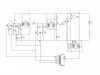
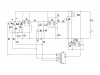
I need your help plz. I have made the siren circuit but I used discrete 555 timers bcos I could not find the um3561 ic. But I have a problem with the switching again, this is bcos with this circuit the first timer acts as a modulator with three selectable resistances between pin 7s resistor and pins 2 ad 6 on a common line, each resistor corresponding to “high low”, “wail” and “yelp” sounds.All these discharge through a capacitor to earth. The ouput pin 3 is connected to a fixed resistor which is in series with two capacitors in parallel for wave shaping. These capacitors are to be brought into circuit ie earthed for only the last two sounds, ant then a commom lie between all three is conected to the control of the second timer timer. Now using the the three outputs from the counters I connected C1815 transistors for switching. For the h-lo it requires no wave shaping so its switches fine, but for the next two sounds I need to switch both the resistor and the wave shaping capacitor but I noticed that the transistor I connect to earth ie its emitter to earth while its collector is to the wave shaping capacitors makes the whole circuit go haywire. The whole switching sequences seizes. I first ganged them that is in twos for the wail and yelp their bases but no way. I separated them no way. Plz hw can I switch both the selected resistor and the gorunded capacitor simultaneously with transistors at the same time. I need a practical solution bcos now the outputs I get do not produce realistic sounds. I read a book and I discovered that using emitter resistors might work but I feel this could affect the time constants of the RCs is this correct? And what values do I use?. As for mosfets I can find no low voltage ones here the best I could find where 2, 50volts ones and this is a 15volts cct.So u see I need to use this xsistors but what is the solution? Thanks
 
No schematic for us to fix?
I don't know why your circuit has counters and I don't understand what the transistors are switching.
 
Gunslingers??

bidex said:
as for HItech and audioguru we learn from our mistakes but if everyone concluded all americans are gunslingers will that be right?
I proudly exercise my second amendment right to bear arms in this wonderful country (USA!!!). Fortunately our founding fathers were not ignorant enough to believe that carrying a firearm means that you must be trigger happy, or otherwise irresponsible. Do you carry wrenches and other handtools around with you? If so, do you wander around town removing lugnuts from the wheels of cars, or removing most of the screws from handrails? Could make for a funny movie, but only a complete idiot would really do it.

P.S. Sig Sauer P239 is a great gun I've had for years. Thankfully, I've never been forced to shoot at a human target with it.

EDIT: audioguru is canadian....and no it would not be correct to conclude that all americans are gunslingers
 
Last edited:
Guns?
We are talking about a siren circuit, not about Americans and their millions of guns.
 
ok here it is

this is the circuit. But note that actually the cd4017 has IN4148 switching diodes on each of its ouputs and pins 3 of its 555timer is connected to pin 14 the clock pin. Pins 8 and 13 are joine and a resistor 15k is connected b/w them and pin 15. From pin a 1uk capacitor is connected to vcc. The problem is that with transistors 5 and 6 connected as shown the circuit siezes to switch or ignores wail sound. But if i remove them and leave only transistors 1 to 3 it switches accurately. The problem is that no wave shaping is then done to both the wail and yelp sound and the sound output is not exactly as it should be. So how do i go about using transistors to achieve this objective?
The transistors are c1815 transistors
thanks
 

Attachments

  • bidex21.jpg
    bidex21.jpg
    47.8 KB · Views: 160
Your transistors don't have series base resistors. So when the base of Q4 or Q5 is driven high to only 0.7V, then the base of Q2 or Q3 can't go high enough to work.

How much current is smoking Q6 with 15V pulses across an 8 ohm speaker? nearly 2A! Luckily Q6 doesn't have enough base current so will pass only about 130mA to the speaker. Maybe your 15V power supply can't supply 130mA and since the circuit doesn't have a supply bypass capacitor then its voltage might collapse.
 
project work

hi Ad,thanks for the reply.I forgot to put the base transistors they are of 220ohms each is this good enough? Also at the ouput i did not amplify with a transistor anymore i just connected it to a 45ohm loudspeaker via a 47uf capacitor but the sound is not very clear wow circuits are really something. So is the problem just the trasistor base resistors values if that is the case what values would you suggets i use for all Q1 to Q5 that would work. Because like i said Q4 and Q5 in circuit seems to kill off everything.
Thanks again
 
bidex said:
I forgot to put the base transistors they are of 220ohms each is this good enough?
The outputs of a 4017 are not strong enough to drive a resistor as low as 220 ohms. It is the same as a short. Use 10k.

Also at the ouput i did not amplify with a transistor anymore i just connected it to a 45ohm loudspeaker via a 47uf capacitor but the sound is not very clear
With a 15V supply, the output of the 555 will swing up to +12.5V and down to +0.5V for 12V p-p. That is only 400mW RMS into 45 ohms at the fundamental frequencies.

The output is a square-wave so the wave-shaping capacitors won't make any difference. you need a linear amplifier driving the speaker to hear wave-shaping.
 
Last edited:
cool

Ad,i think you mean five 10K resistors each connected to the base of each transistor but i want to be sure.Then a whole 10k; both transistors will come on simulteneously with this i thought the current will be too small for such values.What i want to confirm is that connecting the transistors as ie noe for each transistor base and not just three form the counter outputs will make both Q2 and Q4, Q3 and Q5 On at the same time when their respective counter outputs are HiGH hence no switching problems?
I once connected a second clock generator and counter in synchronism with the first and used only the last two inputs to drive Q4 and Q5 but no show so i hope this is the way out.
Well as for the output i think i'll just forget about amplying it, the sound is loud enough so take no notice of the circuit there but i did not really get your jist there though, bcos i do here all three sounds with waveshaping...
The 47uf capacitor does no wave shaping ..well ..
Ad thanks a lot i'll try the switching thatz what i need and i pray it works perfectly and hopefully next time it,ll be another stuff i wonder how u guys got to know all this stuff whats the secret
I will try to post the circuit later i am having problems loading it invalid name or something
 
bidex said:
Ad,i think you mean five 10K resistors each connected to the base of each transistor but i want to be sure.
Each transistor needs a 10k resistor in series with its base to limit the base current.

both transistors will come on simulteneously with this
Q1 will turn on by itself, Q2 and Q4 will turn on together because they are connected together and Q3 and Q5 will also turn on together.

i thought the current will be too small for such values.
If the pins on the transistors are connected properly then they have a high current gain so a small input current through the 10k base resistor results in a high collector to emitter current.

What i want to confirm is that connecting the transistors as ie noe for each transistor base and not just three form the counter outputs will make both Q2 and Q4, Q3 and Q5 On at the same time when their respective counter outputs are HiGH hence no switching problems?
Yes, but the diodes do not allow the 4017 to turn off the transistors. A 100k resistor to ground is needed to turn off the transistors.
 
thanks,but where do i put the 100k resistor and how many?at the emitter of Q4 and Q5 to ground?or where.
Because i noticed what i think u are imlying;when Q2 and Q5 comes on in seems to remain On and affect the other sounds.Anyway the diagram i said i,ll send is here so umm where do i place this 100K resisitor(s) in this diagram.
 

Attachments

  • bidex21.jpg
    bidex21.jpg
    52.5 KB · Views: 156
Last edited:
bidex said:
thanks,but where do i put the 100k resistor and how many?at the emitter of Q4 and Q5 to ground?or where.
Because i noticed what i think u are imlying;when Q2 and Q5 comes on in seems to remain On and affect the other sounds.
The 10k resistors are correct.
Your schematic is still missing the diodes that prevent the outputs of the 4017 from shorting themselves.
Add a 100k resistor to ground at the cathodes of each group of diodes. Three 100k resistors are needed.

The transistor that is driving the speaker has a high collector current (329mA) but has hardly any base current (1mA) so the sound won't be loud and the transistor will get very hot. Use 680 ohms for the base resistor instead of 10k so the transistor turns on as hard as it can.
 
I hear u Sir,so with this i expect to get three distinct sounds without interference from another,since eg when the output for Q2 and Q4 is HIGH they are ON and when LOW they are totally OFF-not affecting d other sounds?And they'll ON again d 100k resistors not preventing this or any other thing.I'll do it and send d updated diagram, i believe it'll work. Thank U.
 
Last edited:
Status
Not open for further replies.

Latest threads

New Articles From Microcontroller Tips

Back
Top