Electro Tech is an online community (with over 170,000 members) who enjoy talking about and building electronic circuits, projects and gadgets. To participate you need to register. Registration is free. Click here to register now.
Welcome to our site! Electro Tech is an online community (with over 170,000 members) who enjoy talking about and building electronic circuits, projects and gadgets. To participate you need to register. Registration is free. Click here to register now.
so would that sun glass looking stuff they use on remotes and tv's to cover the ir sensors, would this defy this problem? my downlights there colour temp is 2700K witch is pritty much yellow light :S
i've haft made it and just double checking the voltages and i get 5volts no hand , 4.85 volts hand in front right where i want it. what resisters do i have to change from 4.5v to 4.85V?
No changes should be required, I will recheck the circuit with these new values.
Have you made any changes to the Emitter/Detector layout, that has caused 4.5V to 4.85v difference.?
Have you checked the output of the LM393 & CD4013.???
nah theres no change i was just trying to get it as far away with my hand as possible with out it being to sensitive i did add a 5v reg coz i know how touchy op amps are
nah theres no change i was just trying to get it as far away with my hand as possible with out it being to sensitive i did add a 5v reg coz i know how touchy op amps are
so would that sun glass looking stuff they use on remotes and tv's to cover the ir sensors, would this defy this problem? my downlights there colour temp is 2700K witch is pritty much yellow light :S
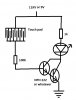
hey man all wired up and its not toggling, i got like 1.7volts at the base of the transistor and even when u make it drop below 4.5v it still doesnt toggle on and off, idk what to do for fault finding. triple checked my wiring. the "comparator " has 12volts at pin 1 and yeah idk what to do :s
[QUOTEhey man all wired up and its not toggling, i got like 1.7volts at the base of the transistor and even when u make it drop below 4.5v it still doesnt toggle on and off, idk what to do for fault finding. triple checked my wiring. the "comparator " has 12volts at pin 1 and yeah idk what to do :s ][/QUOTE]
If you have 1.7V at the Base of the transistor, it suggests that you have the transistor wired incorrectly, or the transistor is faulty.
so yeah theres nothing wrong with it just it hates light in a shady area it works okish but yeah wouldnt really work in the practical way i would like it, theres way to much light :/ thanks for all your help Eric
hey , i wana use your toggle circuit for something less problemy im not quite sure how to re arrange the comperetor but i want to keep the toggle part and replace the ir led and sensor with this.
This site uses cookies to help personalise content, tailor your experience and to keep you logged in if you register.
By continuing to use this site, you are consenting to our use of cookies.


") i'll let u know how i go when i make it and probs put it on youtube like my clapper
i'll let u know how i go when i make it and probs put it on youtube like my clapper