Continue to Site

Welcome to our site!

Electro Tech is an online community (with over 170,000 members) who enjoy talking about and building electronic circuits, projects and gadgets. To participate you need to register. Registration is free. Click here to register now.

  • Welcome to our site! Electro Tech is an online community (with over 170,000 members) who enjoy talking about and building electronic circuits, projects and gadgets. To participate you need to register. Registration is free. Click here to register now.

Help with a LED flasher circuit. Schematic inside.

Status
Not open for further replies.

oneslowz28

New Member
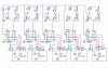
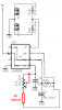
I am very new to this and wish to build a circuit that will flash 5 pairs of LEDs at variable rates. To do this I designed a circuit using 5 NE555 timers. To control the variable flash rate I want to use trim pots. I am having a hard time figuring out where to lay out the trim pot and what value to use. Can some one please help me? I have attached a screen cap of the schematic I designed in eagle.

**broken link removed**
 
I've had a couple of beers, so maybe I'm not seeing this right, but it looks to me as if the top row of Leds are the wrong way round. It looks like the lower row will light when the output is high, but if the top row is meant to light on output low, they are the wrong way round.
Back to my beer :D

Jim
 
Yes, all the LEDs are shown backwards.
Also, a resistor is missing at each 555 from pin 7 to the positive supply that would have a trimpot in series to adjust each frequency.
The 10uf capacitors must be connected to ground.
The circuit should have a supply bypass capacitor.
 
As noted above, there are several errors in your schematic. Here is an online calculator so you can choose your timing component values:
**broken link removed**
 
Thanks for the replies guys. As I said I am very new to this and designed the schematic in eagle after watching a few tutorials. I am basing my electronics knowledge off of 3 electronic classes I took back in high school. After 7 years the knowledge gained in those classes has faded somewhat. The season I had not completed the circuit is because I was waiting on figuring out what value trimpot to use.

I will make the revisions to the circuit tomorrow.

Again thanks for all the help and I look forward to spending more time on this site.
 
Thanks for the replies guys. As I said I am very new to this and designed the schematic in eagle after watching a few tutorials.

Why don't you look at the datasheet (from a manufacturer) for a 555? It has the circuit and the formulas that are needed to make an oscillator correctly.

Some tutorials and most Instructables are made by people who know nothing about electronics.
 
The tutorial I spoke of was a tutorial on how to use Eagle, not on the flasher circuit. My current knowledge on circuit design comes from some classes taken back in high school and most recently reading a few of Forrest Mims books.

I have revised the circuit per every ones input and will post the new schematic shortly.
 
Here is the revision. I think I got everything right this time. Thanks for being understanding with me and for all the help.

**broken link removed**
 
Your schematic is a negative. I fixed it. You saved it as a fuzzy JPG file type instead of as a very clear GIF or PNG file type so that is why it looks fuzzy.
LED 7 is not connected.
The pots are only 1m ohms which is only 0.001 ohms. Maybe they should be 1M which is one million ohms.
The datasheet for the LM555 shows two supply bypass capacitors. A 0.1uf ceramic disc and at least 1uF. Each 555 should have a 0.1uF ceramic disc and the entire circuit should have 100uF.
 

Attachments

  • led_flasher_v102-1.jpg
    led_flasher_v102-1.jpg
    55.9 KB · Views: 419
I have the background set to black in Eagle. I am a professional photographer and almost all of my photo editing work is done on a black background as it is much easier on the eyes. When I found out I could change the workspace in eagle to black I did. I just was to lazy to change it back to white before taking the screen cap. I saved it as a quality 90 jpg and on 4 of my computers it looks fine, but for every ones convenience I will save them as .gif from now on.

The pot's are 1M ohm. I just thought 1.0M was the correct way to write it.

I also notice that LED 7 was not connected right after posting it.

This circuit will be powered by a pc power supply so is the 100uF necessary to filter out noise or does the pc power supply do a good job of filtering anyway?
 
I saved it as a quality 90 jpg and on 4 of my computers it looks fine, but for every ones convenience I will save them as .gif from now on.

For screenshots like this, GIF and PNG are 100% perfect, and also MUCH smaller than a fuzzy JPEG. JPEG is for photos, not computer generated images, and it's rubbish on computer images.
 
For screenshots like this, GIF and PNG are 100% perfect, and also MUCH smaller than a fuzzy JPEG. JPEG is for photos, not computer generated images, and it's rubbish on computer images.

For photos that will be used on the web I resize to 800x600ish then I use photoshop's save for web feature and save at 70% jpg or 32 color .gif Both make for a very small file usually under 60kb but sometimes in the 90kb range.


Here is the latest revision. I replaced the individual LED's with small Mate-N-Lok connectors so I can move the LED's off the board and place them around inside the computer. I also added a 100uF Decoupling cap and a Mate-N-Lok 4pin HDD connector for ease of power hookup inside a computer case. **broken link removed**
 
Last edited:
Your 1M pots do not have a variable resistance because their slider pin is not used. Connect the slider to one end. Each pot should have a resistor in series to prevent it from being adjusted to zero ohms.
 
You mean: connect the sweaper to one of the end leads of the pot or wire a resistor in series and connect the sweeper to one end of that resistor?
 
Do it like this for each 555 circuit:
 

Attachments

  • 555 driving LEDs again.PNG
    555 driving LEDs again.PNG
    10.9 KB · Views: 342
I would like to thank everyone for all of the help notably Audioguru for all of his help.

Here is the final revision.
**broken link removed**
 
Last edited:
Status
Not open for further replies.

Latest threads

New Articles From Microcontroller Tips

Back
Top