Continue to Site

Welcome to our site!

Electro Tech is an online community (with over 170,000 members) who enjoy talking about and building electronic circuits, projects and gadgets. To participate you need to register. Registration is free. Click here to register now.

  • Welcome to our site! Electro Tech is an online community (with over 170,000 members) who enjoy talking about and building electronic circuits, projects and gadgets. To participate you need to register. Registration is free. Click here to register now.

Help w JFET static detector

Status
Not open for further replies.

Trent

New Member
Hello, this is my first post here. I recently built several models of a JFET static detector. All work, but the last version is giving some readings I can't explain. I'll post some facts, thoughts and observations here and I'd appreciate comments on whether I'm right or wrong and what might be happening. This is my first electronics project in many years.

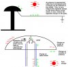
According to the articles that accompany this type of static detector, the antenna is supposed to have the same polarity as the electric field, i.e. a negative object makes the unit respond as if the gate is charged negatively. This is seen on smaller models I made and for the larger model while it was on the breadboard. However, in the final set-up, a negatively charged object brought near the antenna causes a positive spike. First of all, nothing appears to be wired backwards, and I have tried changing the JFET.

Positive charges would be drawn onto the antenna by the nearby negative object. This is how normal electrostatic induction works, as I am familiar with it. But then, what was happening in the small models which gave the opposite response?

Could it have something to do with the small models having a wire as an antenna and the large model having a large (17'' diam) metal bowl?

It can't have to do with the distance between the antenna and the FET gate, or the presence of the cable between the antenna and indoor unit.

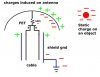
In the small models, antenna and FET gate are extremely close, a fraction of an inch. In the large model, There is only a few inches distance, and the FET is under the antenna bowl so is shielded by it. The 50' cable has a grounded shield and contains wires for the FET source and drain, not the gate.

With normal induction, if a negative object approached the antenna, positive charges would accumulate on the antenna, attracted to the negative charge nearby. Negative charges on the antenna would be repelled to the farthest point, in this case, to the gate. Therefore, the gate ends up with the same charge as the object which approached. So, how would the gate be charged oppositely in my final setup?

Thanks.

Additional Info:
The "smaller models" I mentioned consisted simply of a 9V battery, one nJFET, and one LED. The antenna on these was just the FET gate wire sticking up in the air. Bit by bit I added everything else to this basic tiny circuit. BTW, the unit is powered by a small plug-in power supply that puts out ~9 VDC at 200 mA. The unit only uses 2 to 6 mA. I did not draw the transformer for the pwr supply.
 

Attachments

  • Induced charges.jpg
    Induced charges.jpg
    26.9 KB · Views: 869
  • Wheatstone Bridge part of circuit.jpg
    Wheatstone Bridge part of circuit.jpg
    101.4 KB · Views: 1,507
  • Schematic 10-4-19.jpg
    Schematic 10-4-19.jpg
    136 KB · Views: 2,282
Last edited:
Please post a schematic and a photograph if you can - it's difficult to tell form a verbal description.
 
A schematic has been posted and here are more explanations.

I don't know if there is any filtering on the power supply, but it does not matter. The heart of the unit is a Wheatstone Bridge. As long as there is enough voltage and current, it matters little if the voltage varies. Also, the bridge automatically filters out any common mode interference such as ripple. The bridge consists of the two 50K pots, the 5K pot set for 1100 ohms, and the detector JFET. The bridge has a "positive" voltage drop across the meter terminals when the detector FET has a positive charge on the gate and is conducting. The bridge has a "negative" voltage drop when the FET gate has a negative charge and is turned off. That's when the other FET and LED conduct.

One jack is a chassis ground. Another (Vfc) has a neon tube connected between the circuit (which floats) and the chassis. If lightning is extremely close, the detector FET will be burned out and the high voltage on the antenna can come in through the drain and source wires in the cable and could charge the circuit. At 70 volts, the neon tube will conduct and short the circuit to ground. If I see it light up, it means get out of there fast. Other jacks are for the antenna cable and to plug in a DVM.

I put in a switch that would connect, open or short the detector FET because I didn't know if I would need to zero the unit with the FET in the circuit or not. I also tried to connect a dummy load to try and equalize the zero points with and without the FET in the circuit, but that just made things worse for some reason. As it is, I just zero it with the FET in the circuit. These are not a problem.

The problem is that I'm getting an output on the meter that is the opposite of what I expected. I bring a negatively charged piece of plastic near the antenna and I get a voltage drop indicating a positive gate voltage when the same circuit had turned the red LED off and the yellow LED on when in the breadboard stage which indicates a negative gate voltage. The gate is good to 25 volts. Gate current is 10 mA, reverse current is 2 uA. Drain-source current is about 6.6mA now. The most voltage I've measured on the gate (with this circuit) has been 0.1 volts during fair weather. I have not had any thunderstorms here yet to test it with.

The FET conducts (or not) in one direction. The positive and negative voltage drops are across the Wheatstone Bridge.

The FET can be damaged by excessive gate voltage. I've tried using zener and other diodes as a means to drain excess voltage away from the antenna before it reaches 25 volts, but anything I connect to the antenna reduces the sensitivity to the point of uselessness. It is very sensitive to capacitance.

I added a schematic with the Wheatstone bridge sections highlighted.

More info:
The unit correctly detects a positive atmospheric charge during the day, which drops at night. But I get the opposite response when I try to test it with charged objects.
Also, bringing a negatively charged object near the gate should turn the red LED and FET off. It will come back on when the charge is removed. Positive charges brought close don't exactly cause the opposite effect. The red LED will get brighter as the FET conducts more, but the LED and FET stop conducting when the positive charge is moved away as if the FET was now sensing the CHANGE in the electric field rather than polarity of the static field. The field is changing in a negative direction from positive to zero but the LED and FET go off, not just to zero voltage operation. Nobody who has written about this type of circuit has had an explanation for this. I can add links to the original articles I saw. They will explain more than I have here about the basic operation of the FET detector.
Build this simple "electronic electroscope," a FET electrometer
Avoid the Shock of Shocks! Build Your Own Super-sensitive Electric Field Detector
 
Last edited:
This series of events can account for the meter responses I've seen and it seems possible, though I don't know how probable it is...

As the antenna is approached with the test charged object, the cable betwen antenna and house is passed. At times I'm closer to the cable than the antenna.
A positive charge can be induced on a section of cable shield.
The charged shield would, in turn, induce negative charges on the drain-source wires within.
If the drain and source are negative, they can induce a positive charge on the gate.
Parts of the antenna are positively and negatively charged and these charges do not conflict with the charges coming from the shield.
The result is that when the negative test charge is brought close, the gate ends up positive relative to the drain-source.
When detecting atmospheric charges, this does not happen because the cable and antenna are at equal distances and the antenna is much larger so its charge dominates any charges from the cable.
See attached diagram.
 

Attachments

  • Possible explanation for observed responses.jpg
    Possible explanation for observed responses.jpg
    66.6 KB · Views: 575
I just realized that after rubbing the piece of plastic to generate a negative test charge, I may have retained some residual positive charge. The antenna could be reacting to my approach more than to the relatively smaller piece of plastic. Another possibility.
 
I don't have time to help fully but I would imagine that the charge on the dome will be the same as the object next to it.

I've built a simple meter like this using an N JFET before but it only worked with negative charges.
 
I don't have time to help fully but I would imagine that the charge on the dome will be the same as the object next to it.

I've built a simple meter like this using an N JFET before but it only worked with negative charges.

No. Dome charge is not the same but gate potential is so output looks like charges are the same.
With electrostatic induction, the approaching charge attracts the opposite charges to it and repels like charges. If the like charges have a path to leave the bowl (or whatever), they will, leaving the opposite charges on the bowl. If the approaching charge touches the bowl, then it transfers charge directly, not through induction and the charges will be the same. I know articles say the charge on the bowl is the same polarity as the electric field it is exposed to, but this is opposite how induction really works so I think they are just simplifying things. I have broken it down to show where al the charges go.
 
Status
Not open for further replies.

Latest threads

New Articles From Microcontroller Tips

Back
Top