Continue to Site

Welcome to our site!

Electro Tech is an online community (with over 170,000 members) who enjoy talking about and building electronic circuits, projects and gadgets. To participate you need to register. Registration is free. Click here to register now.

  • Welcome to our site! Electro Tech is an online community (with over 170,000 members) who enjoy talking about and building electronic circuits, projects and gadgets. To participate you need to register. Registration is free. Click here to register now.

HELP URGENTLY NEEDED (will pay ££)

Status
Not open for further replies.

TomLorton

New Member
Im currently in the middle of a product design degree and need help on the electrical side of my project.

I have had help already but am having trouble understanding the circuit diagram. I have little electronic knowledge and require a component list with very simple instructions.

what im trying to acheive in short..

I have adapted a normal socket extension so depending on the amount of voltage/current used will controll tri-coloured LEDS.

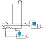
If anybody could help it would be much appreciated and rewarded. I have attached a picture of the circuit diagram some one has drawn up for me...bt i am unable to make much sense of it (e.g i dont know how to apply it to the rest of the circuit or what much of the component sybols represent)

Thanks in advance

Tom Lorton
 

Attachments

  • diagram_385.jpg
    diagram_385.jpg
    17.6 KB · Views: 831
1) the circuit drawn isn't showing much of a function. Ask your friend to redraw the circuit with the following modifications: resistance values, and pin designations (or at least pin numbers) for the bridges.

2) State exactly what you want to achieve. Include what you want in each scenario. For example, what do you want to happen if power is applied, what do you want to happen if the polarity is inversed, etc, etc.

It looks to me that all you have is a heater circuit, and depending on the resistance, the coil at the end could break due to excessive current.

the zigzag symbols represent resistors which change voltage to current and current to voltage. They protect your circuit from frying if they have a high enough value. The arrow with a line at the end of it represents an LED (light emitting diode). These are connected one way and light up when enough current passes through them. The item next to that (top of two capital T's connected together) are non polarized capacitors. Because they are connected with the LED in parallel, the LED won't turn off instantly when power is off because the power is still in the capacitor which is still lighting the LED. Higher capacitor values increases the delay.

If I remember, all a bridge does is convert AC to DC current with 4 diodes connected together.

The L must represent Line and N being neutral. Are you making a device you plug directly into a wall, or are you making it battery operated?
 
thankyou.

hi mstechca,

thankyou so much for replying, you seem to have the ability to speak my language! (thats meant as a complement by the way)

i will ask my friend of friend to include values etc, however i understand he is a busy person and it took a while for him to reply with that.

keeping it simple-

the effect i am attempting to demonstrate is the over consuption of electricity in the home.
the finished unit is a free standing 5x socket extension that plugs directly into mains.

tri-coloured leds (housed inside the socket casing) indicate the Total current drawn by various devices plugged into it.
lots of High drain devices e.g computers,heater = a red colour
fewer devices/things on standbye or things like phone chargrers = a green colour.
ideally the colours would phase nicely between these two extremes with diff levels of current used.

i have been told this isnt too complicated to do??
the problem is this has to be made quite soon. the casing is pretty much done and the guts of socket outlets are ready to be wired.

an alternative i would settle for is a system where the colour changes depending on the number of sockets in use rather than the total current drawn. the first would be ideal but if this is alot easier i think demonstrates the same principle.

i hope this is a bit clearer, its a strange one i admit.

in your expert opinion can this be done by a novice with a couple of relatively smart friends in a weekish?

thanks again and again and again.

tom
 
the effect i am attempting to demonstrate is the over consuption of electricity in the home.
I think you should save your money for hydro ;)

the finished unit is a free standing 5x socket extension that plugs directly into mains.
It will almost be that way when you want extra features.

tri-coloured leds (housed inside the socket casing) indicate the Total current drawn by various devices plugged into it.
lots of High drain devices e.g computers,heater = a red colour
fewer devices/things on standbye or things like phone chargrers = a green colour.
make that bi-coloured LED's.

ideally the colours would phase nicely between these two extremes with diff levels of current used.
i have been told this isnt too complicated to do??
the problem is this has to be made quite soon. the casing is pretty much done and the guts of socket outlets are ready to be wired.
an alternative i would settle for is a system where the colour changes depending on the number of sockets in use rather than the total current drawn. the first would be ideal but if this is alot easier i think demonstrates the same principle.

Turns out that you want a special power adapter. I haven't done your idea before, but I can take a guess at the solution.

Every circuit connected to a power source has some kind of resistance to it. Your best bet is to connect one line from the power source to the units that are being plugged in.

I think it is better to settle for the second, because in my opinion, the 2nd idea will save you money.

Basically, you will need two decade counter IC, a clock circuit (there are billions of these on the net), and 5 AND gates, 1 for each socket.

When your circuit is done correctly, an internal clock will pulse at a constant speed. At the clock rate, the decade counter will increment by 1. As soon as it reaches 6, the clock is reset to 0, and both counters reset. If the clock is between 1 and 5, it will compare the corresponding socket number. if the socket number is used (has a low resistance), then the AND gate produces a high output. As soon as any AND gate produces a high output, another counter increments by 1.

But since you are dealing with high voltages, I doubt that you can just get away with AND gates. I think you will have to work with transistors.

Are you using 120 or 240 volts?

I dont know if any chip can handle such voltage.
 
I'd do this with a current transformer. Current transformers let you measure the current on an AC line without connecting to mains voltage. Depending on what currents you are working with there might be enough current coming off the current transofrmer to run your LEDs.

You can buy current transformers at www.digikey.com. Also Radioshack probably has clip on devices like a multimeter that you could modify.
 
The voltage across the mains isn't going to change. Basing your location on the £ in the subject line, your voltage is going to be 230v AC. What you need is a device that measures current. If the device is going to be connected in series with your appliances, any current going through the appliance is also how much is going through your device. Heaters and dryers and such use a lot of power. You could have a 1600w hair dryer using 7 amps that you're going to have to deal with. And that's just for the dryer alone. Anything in addition that you have plugged in is going to just add more! If you decide not to test anything that extreme, but stick with a computer as your upper limit, that's still going to be around 400w, around 1.73 amps. Yes, that is more manageable to work with, but you may have to look around to find components able to handle that.

Plus, if you don't know what a resistor or a diode is in that diagram, what in the world are you doing trying to develop high power measuring equipment and plugging it into a wall?
 
The circuit you posted is not viable.

bmcculla said:
I'd do this with a current transformer. Current transformers let you measure the current on an AC line without connecting to mains voltage.

I agree that a current transformer is a possible solution. But be careful!

Current transformers can be dangerous.

Also, you have to put it in series with the house mains supply. So you would have to do this at the fuse board. Do you have fuses or circuit breakers?

If you have fuses, you can remove one and plug a suitable device into its socket.

However, if all you want to know is the power consumption of various devices, you could either read the power meter or connect an AC Ammeter in series (remove a fuse) and measure the current.

There are some complexities that you will not appreciate given your limited knowledge. So if you keep posting your thoughts, we can help further.

Len
 
thanks to everybody replying, seems there is a few possibilities.
im looking for the one thats simplest to make using as standard as possible components (to reduce lead time on parts).

am starting to understand the theory of using a current transformer. LOVE the relative simplicity of the idea, also very keeping with the idea of energy conservation.

www.hvcomponents.com also seems to have what im after, im hoping to find a company like this that can provide a unit ready made to suit my spec?

does such a place exist? could you estimate a lead time on sourcing components?

to those who question my ability or intent, i see your point clearly. i do however have the ability to learn v.quickly and although i may struggle with general terminology if you can understand the physical process thats what really counts.

thankyou all
 
bonxer said:
The voltage across the mains isn't going to change. Basing your location on the £ in the subject line, your voltage is going to be 230v AC. What you need is a device that measures current. If the device is going to be connected in series with your appliances, any current going through the appliance is also how much is going through your device.

But the real power consumption cannot always be shown by measuring current alone. If it's an inductive or capacitive load part of that is imaginary power which is not what you want to measure.

Also note the differences in peak current versus rms current in nonsinusoidal current consumption. In a device powered by a rectifier and capacitor, you may see some high peak current which is much more than the rms value.
 
Also, you have to put it in series with the house mains supply.

If you get the right kind of current transformer you don't have to connect it to main voltage. There are current transformers that only have one coil. You wrap a mains wire through the center of this coil to form the other side of the transformer.
 
This thread is going nowhere.

The OP simply wants to light LEDs based upon current magnitude inside an AC extension socket and that can be done easily with a resistor in the neutral return lead. Did he mentioned he want to measure power? Does peak or rms make any difference?

Why were the talking of current transformer or suggestions like "not connecting to the AC main"? How else would you power the circuit, leds, using batteries? The circuit is going to be inside the extension anyway and is not within reach of the poking finger. What difference it would make to have contact with live, main voltage?

A capacitive voltage dropper, rectifier, zener and capacitor, LM339 comparator, LEDs and you are done. Sorry I'm a bit dumb.
 
Status
Not open for further replies.

Latest threads

New Articles From Microcontroller Tips

Back
Top