Continue to Site

Welcome to our site!

Electro Tech is an online community (with over 170,000 members) who enjoy talking about and building electronic circuits, projects and gadgets. To participate you need to register. Registration is free. Click here to register now.

  • Welcome to our site! Electro Tech is an online community (with over 170,000 members) who enjoy talking about and building electronic circuits, projects and gadgets. To participate you need to register. Registration is free. Click here to register now.

HELP: Un-isolated Power supply problem

Status
Not open for further replies.

abicash

Member
Hello

In my current project , i am building a proxy sensor using a CY8CMBR3102

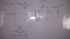
The power for this circuit is a capacitive un-isolated standard circuit.There's a +12v for a relay and there's a +5v for the CY8CMBR3102 and a small Microcontroller.

The proxy sensor is a single layer square sized board creating a capacitance of 12pf.
The general principle of the cypress device is of measuring the capacitance of the sensor, which increases when a finger or a hand or metal is brought near it. It triggers a relay through a transistor and toggles it on the next proxy event.

The problem arises when the Line and Neutral are reversed at the board.
The CY8CMBR3102 thinks there's dynamic capacitance variation at the sensor , and starts auto toggling the relay.
I am unable to draw any sane conclusion from the phenomenon.
Can someone throw some light?
 
The problem arises when the Line and Neutral are reversed at the board.
One problem could be electrocution of the owner of the finger :eek:. Why aren't you using an isolated supply?
 
There's not much space where this is going to work.
No scope of any kind of switching or LF transformer.
Apart from the electrocution hazard, can you beam me to the problem?
 
The situation is slightly different depending weather you are using full wave rectification or half wave rectification but the results are the same. The hole electronics unit is basically connected to the live of the mains supply so the input sensors will see a 240 volt AC signal on the sensors when someone is near them. This is because the person will be at ground potential. The sensing circuit is not designed to deal with such a large amplitude AC signal.

I totally agree with Alec that YOU SOULD NOT USE THIS DEVICE WITH SUCH A DANGEROUS POWER SUPPLY DESIGN.

Les.
 
You are asking me to diagnose a signal integrity problem between an undocumented power supply and an undocumented application circuit, with no information about the application or its operating environment. I'm glad you have such a high opinion of my skills, but you are wrong; I'm not *that* good.

You have been a member here for 9 years. In that time, how often has someone asked a question, only to be asked back for a schematic?

ak
 
Also if you use a galvanically isolated supply then you will be able to reference the circuit common to earth ground if needed.
Max.
 
or just wire it in right.
Yes that's one way :)

AnalogKid
How is that most of the learned members understood the problem without looking for a schematic?
Please comment if you have something meaningful to add to the conversation, otherwise just ignore it.
Please don't treat the above request as written with any bitterness
 
abicash,
AnalogKid's motive is so he may be able to come up with a solution to your problem. It is you that is being unreasonable by not providing enough information. For example they type of microcontroller that you are using will give us an idea of the total current required. As well as the schematic, information about the application this device is to be used for could help to find a solution. I have a theory about the explanation of the symptoms but without the schematic I cannot say if the theory is correct or not. I still think it is dangerous to use this type of power supply for your application and I don't think it would meet safety requirements in any country.

Les.
 
I have produced devices that live on the power line and passed UL, CSA VDE safety.
There needs to be two layers of insulator between a person and the wires in your project.
There needs to be a way where a child and a fork can not get connected to power.
I had problems passing the "balling ball" test. They connect a rope to a heavy ball and drop the ball onto the project. There must be no openings open up so a person could get endangered.

These tests are really no different than any product with power line wires inside.
If there are buttons or something for a human interface it is harder.

If you are building for a hobby.......be safe. Just remember wires get mixed up and you need to live a long life. LOL
 
AnalogKid
How is that most of the learned members understood the problem without looking for a schematic?

You have made yet another incorrect assumption. I understand the problem, I know what is causing it, and I know how to fix it. None of which is the point. There were only two responses before mine, one question and one explanation of how your circuit is supposed to work. Neither of those indicate that the writers "understood the problem" and neither was any hint at a solution.

My point was that you don't know how to ask a favor, and you should. Without some actual engineering information, this thread will continue to wast the time of generous strangers while not generating any useful result. This is an electrical engineering forum, not the psychic hotline, and you have know that for nine years. You've read other threads, and know how things are done around here. Act like it. If you want to communicate with professionals, make an effort to speak their language. In this case, you can take some guidance from Admiral Josh Painter in The Hunt For Red October,

What's his schematic, son? An engineer don't take a dump without a schematic.

ak
 
Last edited:
So what's the hard part ot figure out? You hook it up wrong and it doesn't work properly?

Maybe you can help me out?

Yesterday I got in my vehicle and instead of putting it in Drive I put it in Reverse and it didn't go forward like I thought it should. I have no sane reason for why its doing that now so any thoughts on what is wrong? o_O
 
OK.
This thread is becoming everyone's ego ride it seems.
I definitely know how to ask a favor, and have been doing that for many years. Wherever necessary I have provided my schematics, codes and whatever information required to explain my case.
This time though I felt that most will understand when I say "Capacitive" un-isolated power supply.
Here's one attached which I have used.Although it's a photograph of the one I drew on a white board , so please forgive me for not providing a Cad sch.
Secondly , the un-isolated board is going to be fixed in a wall,then there's an overlay ,which is isolated. After which there will be another granite tile over all this assembly. In no way is it electrically available to any user. The proxy sensing will happen at a distance of 10 cm. Even if the tile is touched, it is fully isolated.
Thirdly, the electronic switch used is an electromagnetic relay. So the lamps or any mains operated device is switched through this relay contact.
ronsimpson
Thanks for the information. It's useful.

With all the information on this thread, no one is actually helping me with MY PROBLEM though.
The problem is, that when I reverse the Line & Neutral to the board, the cypress device starts toggling the relay.
Please look for the Cypress device data sheet in my original post.
Finally I would like to say that I understand that this is a technical forum. And people here are helping out each other without any benefits.
Analog Kid , I apologize if I have been a bit overbearing , never my intent.
Although please don't be sarcastic.
It would have been worth the while if you had never brought my 9 years age and how immature I am. Instead if you had directly asked for the schematic, I wouldn't have been the ass in arguing with fellow members.
Thanks and regards
 

Attachments

  • IMG-20160304-WA0010.jpeg
    IMG-20160304-WA0010.jpeg
    666.4 KB · Views: 206
As you are asking for help we have to assume that your level of knowledge on the subject is fairly low. You could have used a half wave rectification system which would have changed the explanation slightly. You could also have made errors in the design of the circuit.
Here is my explanation of the problem.

Neutral will be connected to earth at some point. (Probably in the sub station.)
We will assume the mains voltage is 240 volts RMS ( 340 volts peak or 680 volts peak to peak.)
-----------------------------
Situation 1 Neutral connected directly to the bridge rectifier.

When live is on the positive half cycle with respect to neutral the DC - output will be at about + 0.7 volts with respect
to neutral.

When live is on the negative half cycle with respect to neutral the DC - output will be at about - 12 volts plus the volts drop across the 100 ohm resistor. If we assume this voltage drop is 5 volts then it will be at - 17 volts with respect to neutral.

So the negative DC output line is an AC waveform with an peak to peak amplitude of about 17.7 volts. (It will not be a sine wave.) The sensor will see this via the capacitance between the finger and the sensor. I believe this to be the situation were the unit works.
-----------------------------

Situation 2 Live connected directly to the bridge rectifier.

When live is on the positive half cycle with respect to neutral the DC - output will be at about + 340 - about 17 volts (+ 323 volts) with respect to neutral.

When live is on the negative half cycle with respect to neutral the DC - output will be at about - 340 - 0.7 volts (- 339.3) volts) with respect to neutral.

So the negative DC output line is an AC waveform with an peak to peak amplitude of about 662.3 volts. (It will be a distorted sine wave.) The sensor will see this via the capacitance between the finger and the sensor. I believe this to be the situation were the unit does not work.

Les
 
Your schematic shows a 'ground'. Is that a true earth ground, or merely a common point not actually galvanically connected to true earth ground?
 
So, as Les has stated: The sensor needs to sit on (or close to ) ground. It can not function when sitting on a AC power line. The bridge needs to connect to the power line wire with the least noise on it. I don't see a low cost way around that.

1) use a DPDT relay to reverse the power line wires. It requires more current if that relay needs to be on. I have seen latching relays used in transformerless projects like this.
2) There might be a way to use a simple relay and two high voltage caps to do the same thing. Don't have time to think now.

I would use a LM78L05.
 
Your schematic shows a 'ground'. Is that a true earth ground, or merely a common point not actually galvanically connected to true earth ground?
The schematic appears to indicate Chassis ground not Earth ground.?
Max.
 
True, but it's not unknown for ground/common/chassis symbols to be used indiscriminately.
 
I still don't understand why the power and common lines are being reversed?

Even more so if its going to be permanently mounted inside a wall? ? ? o_O
 
Status
Not open for further replies.

Latest threads

Back
Top