Continue to Site

Welcome to our site!

Electro Tech is an online community (with over 170,000 members) who enjoy talking about and building electronic circuits, projects and gadgets. To participate you need to register. Registration is free. Click here to register now.

  • Welcome to our site! Electro Tech is an online community (with over 170,000 members) who enjoy talking about and building electronic circuits, projects and gadgets. To participate you need to register. Registration is free. Click here to register now.

HELP!! TOPWARD DIGITAL DC POWER SUPPLY (TPS-2000D series)

Status
Not open for further replies.

craig-721

New Member
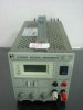
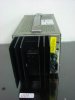
Hi there, i have just bought a topward power supply (TPS-2000D series) for electro plating, but i would like to know a bit more about how to use it properly so i do not break it, I would like to know if anyone knows where i can get some operating instructions from. hope you can help me thanks craig:)
 
Looks like the manual is available here: Topward TPS-2000D, 4000D Manual from Vintage Manuals, Inc.

FWIW: General reference and MY NOT pertain to you.

SENSE LEADS: If there is an S- and S-, they need to be connected to V+ and V- respectively

For plating purposes, supplies are normally operated in CC or constant current mode. The voltage sets the voltage compliance in this case.

If your lucky, there may be a push button to allow setting of the outputs without delivering either current or voltage and a On/standby button

Also power supplies may have the ability to do:
External; Resistance programming
External: Voltage programming
Exterbnal: Current programming

and Master/Slave operation

If this is the case, you'll have to refer to the instructions.

Post a pic of the front and back panel using go advanced/manage attachments and I might be able to help more.
 
Hi thanks for replying these are the photos
 

Attachments

  • 11091016738277_307.jpg
    11091016738277_307.jpg
    46.7 KB · Views: 359
  • 11091016738277_229.jpg
    11091016738277_229.jpg
    36.5 KB · Views: 238
It looks like there is nothing on the rear panel of use. Not sure what the two holes are labeled.

The internal/external switch looks like it allows you to use the meter as an external meter using the red/black below the power switch. Any limitiations would be in the manual.
V or I selects the display of actual voltage or current

You have a course and fine knob for voltage and a single knob to set the current.

I think the white post is labeled (-), the red(+) and the black (Gnd). It's customary to put ground (the third pin of the line cord) at the front panel.

You will need an IEC plug in line cord for the power in in the back.

That's my best guess.

Set it to internal and V with Current somewhere not at the extreme left and the meter should move when you adjust V (Course and fine).
 
Status
Not open for further replies.

Latest threads

Back
Top