Continue to Site

Welcome to our site!

Electro Tech is an online community (with over 170,000 members) who enjoy talking about and building electronic circuits, projects and gadgets. To participate you need to register. Registration is free. Click here to register now.

  • Welcome to our site! Electro Tech is an online community (with over 170,000 members) who enjoy talking about and building electronic circuits, projects and gadgets. To participate you need to register. Registration is free. Click here to register now.

Help to identify 8 pin IC please

Status
Not open for further replies.

Western

Member
Hi guys, I haven't been here in ages ... just wish I had more time to participate.

I am generally pretty successful in identifying unknown parts via google ... but am stomped with this one.

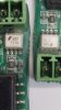
I have a number of boards to repair and one particular IC is giving me trouble.

One board has what appears to be a Fairchild IC marked with the logo and then "600" and "213S"

Second board has the same but "111S" in place of "213S"

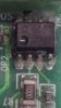
On the remaining boards the ICs have a logo which I can not identify ... appears to be a white circle with nine vertical lines inside it ... though it is that hard to see that it could be a sine wave perhaps ... but fully contained inside the circle.

These are marked with "600" and "002".

Pin 5 is the supply - and pin 8 is 5 volts. Pin 3 is an input from a sensor of some type.

I'm sure it will be a piece of cake for someone ... but so far I've had no luck.

Thanks.
 

Attachments

  • 20180425_102838_resized.jpg
    20180425_102838_resized.jpg
    168.9 KB · Views: 295
  • 20180425_102915_resized.jpg
    20180425_102915_resized.jpg
    141.2 KB · Views: 1,060
It looks (from the shape) like an optocoupler - does that seem likely from the context of the circuit? Some logic-output optos come in an 8-pin package.
 
the white device looks like an optocoupler. The F symbol indicates Fairchild Semiconductor (now ON semi)

Not sure about the other one
 
Thank you Tom and Simon. You gave me the impetus to search again and this time I was successful.

I searched for "fairchild 8 pin optocoupler 600" and checked images. There was an image of my part on the third row.

Turns out it is a HCPL0600 DC Input Logic Gate Output Optocoupler.

I'll add this to my hand drawn circuit and see if I can work out how the board functions.

Wish I had asked earlier ... could have saved a lot of time. :)

Thanks again, much appreciated.
 
Looks like you have an answer. Here are some clues for the next time.

It looks like the reference designator lettering near pin 1 (a common location) is OP2, again leading to an optocoupler of some type. However, that ref des might be for some other nearby component; a wider shot would help. The board was laid out using PADS software. The date code on other components where it is more obviously a date code might confirm that the 2nd line on your parts is the manufacturing date, leaving the first line as the clue to the full part number.

Often, an SMT optocoupler has an asymmetrical body, in that the plastic part above the separation line where the pins come out is thicker than the part below the pins. The black part in the 2nd photo looks like this. This is a way of increasing the "creepage distance", a factor in the part's voltage isolation rating and another clue as to the part's use.

And finally, if you are repairing them, don't you have a schematic and BOM?

ak
 
And finally, if you are repairing them, don't you have a schematic and BOM?

Very often manufacturers won't supply either spares or service information, you're essentially working blind on most equipment now. While I no longer repair TV's, almost all sets for the last few years have no circuit diagrams available, including Sony ones, repair policy is to replace complete PCB's - for the short time they will be available.

I've spend a good part of today doing a little 'reverse engineering' in order to figure out what might be wrong with an item of expensive industrial test equipment - I was working on the battery charging circuit. First port of call is to try and find datasheets for chips and any big transistors. interestingly it used a PIC 16LF819, running at only 32KHz. There was also a MAX471, 3A current sensor, three switch-mode PSU IC's (including a large one on the incoming 12V), plus various other IC's. There were also two biggish P-channel FET's next to each other, near the battery socket - I decided one was switching charging current to the battery, and the other was switching the output FROM the battery to the rest of the circuit. While testing which pin went where, on diode test/buzzer I happily noticed the output switch one was S/C on all pins :D

What I didn't know, as it's been in for repair for a good many months, is that my new boss had replaced a S/C tantalum (with an electrolytic), and the fuse to the battery was also blown - which I could see, as it was missing. The S/C capacitor was on the output of the FET switch, so the capacitor going S/C had obviously taken the FET out, which in turn had killed the fuse.

I've got the duff FET out, and ordered one, plus the Wickmann fuse which has blown, hopefully replacing those will effect a cure. Oh, I've also dropped the battery pack on charge from a CC PSU at 400mA, to see if that's OK or not.

Sorry for the rambling post, but that's what repair work is like now in the 21st century :(
 
I've spent the last 2 weeks (*very* intermittently) reverse engineering the schematic for a DC motor speed control from cell phone pictures of the board. Company was zero help, etc. But I'm in hobby mode. My read of the TS was that this is his day job, hence the question about docs.

ak
 
It looks like the reference designator lettering near pin 1 (a common location) is OP2, again leading to an optocoupler of some type. However, that ref des might be for some other nearby component; a wider shot would help. The board was laid out using PADS software. The date code on other components where it is more obviously a date code might confirm that the 2nd line on your parts is the manufacturing date, leaving the first line as the clue to the full part number.

Mmm ... I dropped the ball there. You are dead right, the OP2 does refer to the part ... there is an OP1 on the board as well and that is clearly an opto.

Now that I have the datasheet, the date codes are obvious too. Good reminders of other things to check when I'm stuck. Thank you very much.

By the way, how on earth did you work out that it was designed with PADS software ... I'd never even heard of that. I just fix stuff ... I'm not into designing. :)

And finally, if you are repairing them, don't you have a schematic and BOM?

Hahahahahahahahahaha ....

That would be nice ... though I don't remember the last time I had that luxury ... I think I had one back in about 2011 or 12. :)

... although having said that ... I have drawn out hundreds of sections of circuit of boards from the equipment I see ... so I do have that for repeat boards.

I regularly add sections as I find faults in other areas ... so they slowly grow.

Unfortunately, I see probably one new style of board every week ... so it's (literally) back to the drawing board and the datasheet roundup to start the merry-go-round all over again. I love my job.
 
Very often manufacturers won't supply either spares or service information, you're essentially working blind on most equipment now.

That is certainly my experience. In fact I feel like I've won the jackpot if I can access a user manual for the equipment. At least I can then work out what the board is supposed to do ... then work out what it is not doing ... so then have a fighting chance of fixing it.

It's nice to know I'm not alone.

Thanks for the help guys.
 
It's nice to know I'm not alone.
Nope... not alone. Same here!

Actually, I thought I'd tried searching for HCPL600 as my first shot-in-the-dark at what it might be - but found nothing, so Western obviously looked harder than I did.

I've embarrassed myself in the same way here, too. Posted at picture if a transistor with the usual "what's this" message... I'd googled high and low for the part number, added prefixes and suffixes, exchanged 1's and i's, 0's and o's etc... and found nothing.
First post was "did you try searching for the other number on the part?". Sure enough, first hit, there was the datasheet. For some reason I'd convinced myself that the second number must be a date code or somesuch, and never even bothered looking for it.
Every day is a school day.
 
It's funny, I had originally searched "Fairchild optocoupler 600" (and variations) and came up with nothing.

But after the prompting from you guys I added 8 pin to the list ... and there it was staring me in the face.

Since I downloaded the datasheet, I've had this nagging feeling I've come across this device before. I'm sure it'll come to me eventually.


Every day is a school day.

Yes ... a bit like the saying ... the more I learn, the more I realise how much I don't know!


Thanks everyone for the help ... I need to stop and ask more often. Been working on my own for too long. :)
 
Status
Not open for further replies.

Latest threads

New Articles From Microcontroller Tips

Back
Top