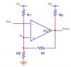
Can anyone please help me with this task and provide step by step formulas in order to calculate the resistors:
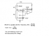
Schmitt trigger given
the following design requirements:
1. You should use the following DC supply rails:
0V, +5V, +10V and -10V
2. The Schmidt trigger should have the following characteristics
Upper switching threshold level = 1.50 ±0.01 Volts
Lower switching threshold level = 1.00 ±0.01 Volts
3. The circuit should be designed to meet the specification over an input frequency from 0.1Hz to at
least 20kHz.
I WOULD REALLY APPRECIATE HELP!