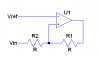
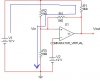
Hi guys,
Anyone know any links to where I can find the formula/expressions for an Op Amp Schmitt Trigger ? Meaning to calculate the UTP and LTP values. Or if any of you know the formula, please reply, this is giving me a headache !
I understand the theory but I just can't get the calculations. I've googled everywhere and I cannot find any .. There are formulas for BJT Schmitt triggers though.
Thanks.
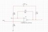
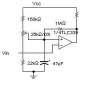