Continue to Site

Welcome to our site!

Electro Tech is an online community (with over 170,000 members) who enjoy talking about and building electronic circuits, projects and gadgets. To participate you need to register. Registration is free. Click here to register now.

  • Welcome to our site! Electro Tech is an online community (with over 170,000 members) who enjoy talking about and building electronic circuits, projects and gadgets. To participate you need to register. Registration is free. Click here to register now.

Help please - mic preamp/mixer.

Status
Not open for further replies.
How low do you want the frequencies? C3, C2c and C2d have cutoff frequencies of only 1.1Hz. Instead of 1uF use 100nF (11Hz) or 47nF (23Hz) film capacitors.

Design the pcb so that the inputs are away from the outputs.
 
<< How low do you want the frequencies? C3, C2c and C2d have cutoff frequencies of only 1.1Hz. Instead of 1uF use 100nF (11Hz) or 47nF (23Hz) film capacitors. >>

Thanks for the headup, Uncle $crooge. You're speaking of the cutoff frequencies of the RC networks that include C3, C2c, and C2d? Right, those networks/filters and their frequencies are a dark unknown to me.

We're talking audio frequencies in the usual 20-20kHz range. Mostly voice, actually, as in YouTube. So going straight to the 47nF, and making a note of the other capacitor values you mention for reference.

Thanks too for the circuit layout note, which will be observed. Construction will actually be on Radio Shack perfboard, their catalog number 276-1396. A 6" x 8" panel for $4. Outrageous, but the best price I've found. Reviews indicate that these boards are cast plastic, as opposed to laminates, but this job is not to military specs.

Radio Shack #276-1396:
Pre-Punched IC-Spacing Perfboard - RadioShack.com

Shielded connecting wire will be used, and the whole assembly housed in a vented metal enclosure screwed/grounded to the computer chassis. A soup can.

- al -
 
Last edited:
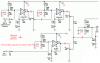
<< Your new schematic does not have a gain control for the mic preamp...My preamp circuit in the Sticky has the 470k pot as its gain control. It adjusts the gain from 1 to 214...Maybe the 150k negative feedback resistor for your 1st opamp should be a pot. >>

That was the plan from day 1. The counters show that some 12,000 people have viewed your Sticky circuit. Certainly tens or them if not hundreds (thousands?) have built it, and been happy, and bragged to their girlfriends, and received their reward, so I figured what can be wrong?

But that was before I ran afoul of Charles Kitchin, waving his degrees and published papers (many). Mr. Kitchin warns in grim detail of the dangers of bias errors, but then offers a solution. And we who keep our pencils in carefully straight lines are influenced by such things.

I would suggest strongly that you ignore the basically rubbish information in that article (as far as audio is concerned), and use the gain pot as used by AG in the sticky. Adding an attenuator after the first stage prevents the second stage overloading, but does nothing to stop the first stage overloading.

As it's an AC circuit you gain nothing by been DC coupled, and it can cause potential problems - which AC coupling would cure.

Long before I ever heard of AG (back in the mid 70's) I built a multi-channel mixer for the PA of a band I was sound engineer for - I too used a similar gain pot, allowing variation from mike levels to line levels on a single input (high impedance, using 50Kohm mikes back then).
 
The capacitors in the signal path each has a cutoff frequency. But their attenuation of low frequencies adds up.
The cutoff frequency of an RC pair reduces the level at that frequency -3dB which is an amplitude of 0.707 times. Lower frequencies are reduced by 6dB/octave. A 6db reduction is 0.5 times.
If C3, C2c, and C2d each has a cutoff frequency of 23Hz and C2a and C2b have a cutoff frequency of 21.3hz and C5 has a cutoff frequency of 16Hz then the total cutoff frequency is 126.7hz and lower frequencies are reduced a lot.

Speaking of capacitors, volume controls R1C1A, Rmic and Rline should be fed from coupling capacitors to keep DC out of them. DC in a pot causes it to make loud scratchy sounds when it is turned.
If the capacitors are 1uF then the total cutoff frequency is 175Hz.
But if all the coupling capacitors have their value increased to 10uF then the total cutoff frequency will be about 18Hz. Voices don't go down to 18Hz, use a total cutoff frequency of about 59Hz with 3.3uF coupling capacitors and increase the 47nF capacitors to 150nF if you can find them or 220nF.

Years ago I used RadioShack perf boards with copper strips on the back. They were made of cheap paper-phenolic that warped, was brittle and the copper was too thin and poorly glued. The holes were much too big.
Then I found Veroboard that was made from epoxy-fiberglass (they had cheap paper-phenolic ones too) and proper copper and gluing. When Veroboard disappeared I used excellent Chinese then Taiwan copies (but they stink).
 

Attachments

  • preamp mixer.PNG
    preamp mixer.PNG
    155.8 KB · Views: 225
Thanks for your comments, Nigel. I read & heed. I'm coming to see that in this audio affair:

1. You can amplify a single frequency at a single degree of gain. But:
2. Anything after that is half science, half art, and half dogged persistence. And:
3. You can't mix gurus.

I'm presently studying audioguru's advice and putting it into practice..."into practice" in the form of altering the schematic. Good thing the schematic's not on paper or it would be in shreds by now. Thanks again.

- Al -
 
Last edited:
Thanks for taking the time and trouble to set me straight, Uncle $crooge.

Unfortunately, I don't think I was able to follow your instructions very well. The attached schematic is what I came up with, but things seem funny.

The input capacitors are now different values. C3 (Mic In) is 150nF, and C4 (Aux Line In) is 3.3uF. This doesn't seem right (for all I know).

The "2" capacitors are now different values. C2a and C2b are 1uF, while C2c and C2d are 150nF. This, too, doesn't seem right (for all I know).

All of this after studying along as best I could, referring back to your mic Sticky, and fooling around with some online RC network calculators. But I lack the underlying knowledge to understand the application of principle, so I just blindly followed instructions...maybe. Or maybe not.

At any rate, I did make IC1a variable gain. There's no such thing as a 150k pot apparently, so I used a 100k pot and a 50k resistor. I kept the 150k total resistance to avoid making unauthorized (by you) circuit changes.

Well, here the thing is. I'll much appreciate your correcting my corrections.

- Al -
 

Attachments

  • mic-aux-preamp-mixer.gif
    mic-aux-preamp-mixer.gif
    56 KB · Views: 238
The calculation of the cutoff frequency of a RC network is 1 divided by pi x R x C. 1/pi is simply 0.16.

I didn't finish the circuit before. I did now.

Which quad opamp will you use?
 

Attachments

  • mic preamp and aux mixer.PNG
    mic preamp and aux mixer.PNG
    193.8 KB · Views: 182
Gasp! Thanks Uncle $crooge! It's like a cloud has lifted.

I'm sticking with the TL07x, and not in quad form. Jameco and those sell a TL07x for 50 cents, which leaves me slack to burn some to death with a soldering iron, connect a few to line voltage, things like that. Mistakes dooo happen.

Probably TL072, possibly TL071 if available. Have you seen the size of components these days? I sharpen pencil points bigger than 1/4 watt resistors, and capacitors are not much better. I don't know where your fingers are supposed to go when you try to work. No wonder they make these things with automatic machines.

In spite of its faults I'll use the Radio Shack perfboard. It's the least expensive I've found, and I fully expect to set fire to a couple of boards. It's not like I had customers and warranties to consider--except the "will you build me one" crowd.

Thanks again for helping me out this way. Plowing ahead and hoping for the best.

- Al -
 
Status
Not open for further replies.

New Articles From Microcontroller Tips

Back
Top