Continue to Site

Welcome to our site!

Electro Tech is an online community (with over 170,000 members) who enjoy talking about and building electronic circuits, projects and gadgets. To participate you need to register. Registration is free. Click here to register now.

  • Welcome to our site! Electro Tech is an online community (with over 170,000 members) who enjoy talking about and building electronic circuits, projects and gadgets. To participate you need to register. Registration is free. Click here to register now.

Help Please! 8x8 RGB LED Matrix with MAX 7219 and Arduino

Status
Not open for further replies.

Lord_Nikon

New Member
Hello all,

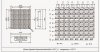
I'm in the beginning stages of a project and am just learning how to use an Arduino Uno with a MAX7219 driver with an 8x8 LED RGB Matrix.

I'm using someone's source code to just get a basic understanding of how to put all these pieces together and will then modify it as I need to.
Source code here: https://playground.arduino.cc/LEDMatrix/Max7219?action=sourceblock&num=1

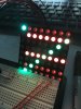
Now, I have only connected the GREEN LEDs on the 8x8 matrix, but when I run the code I get RED LEDs as seen in the attached photo. How is this possible? Have I wired something wrong or is this a possible manufacturing defect of the matrix? The red and blue LEDs are not connected to the breadboard at all.

Any help would be appreciated. Thank you!
 

Attachments

  • 2088RGB-5-datasheet.jpg
    2088RGB-5-datasheet.jpg
    114.1 KB · Views: 681
  • IMG_0733.jpg
    IMG_0733.jpg
    1.4 MB · Views: 404
You must have connections to the LED matrix mixed up. The is no way for proper connections to light tbe wrong color.

Does the data sheet match the markings on the LCD matrix? There is no standard pinout for these things.
 
I'll triple check my wiring after this. I'm 99% sure the schematic is correct, but I'll check that again too.

Before connecting the matrix to the MAX7219, I wired all the green LEDs to 5V through a 330 Ohm resistor. As expected only the green LEDs illuminated.

When I wired them to the MAX7219 (note: not changing any wiring connected directly to the matrix, but rather the wires coming off the matrix were re-positioned on the bread board) and ran the code the picture above is what resulted.

********************************Source Current*********************
Matrix_PIN_17 ---> female to male jumper wire ---> MAX7219_PIN_14
Matrix_PIN_18 ---> female to male jumper wire ---> MAX7219_PIN_16
Matrix_PIN_19 ---> female to male jumper wire ---> MAX7219_PIN_20
Matrix_PIN_20 ---> female to male jumper wire ---> MAX7219_PIN_23
Matrix_PIN_29 ---> female to male jumper wire ---> MAX7219_PIN_21
Matrix_PIN_30 ---> female to male jumper wire ---> MAX7219_PIN_15
Matrix_PIN_31 ---> female to male jumper wire ---> MAX7219_PIN_17
Matrix_PIN_32 ---> female to male jumper wire ---> MAX7219_PIN_22


*******************************Sink Current************************
Matrix_PIN_21 ---> female to male jumper wire ---> MAX7219_PIN_2
Matrix_PIN_22 ---> female to male jumper wire ---> MAX7219_PIN_11
Matrix_PIN_23 ---> female to male jumper wire ---> MAX7219_PIN_6
Matrix_PIN_24 ---> female to male jumper wire ---> MAX7219_PIN_7
Matrix_PIN_25 ---> female to male jumper wire ---> MAX7219_PIN_3
Matrix_PIN_26 ---> female to male jumper wire ---> MAX7219_PIN_10
Matrix_PIN_27 ---> female to male jumper wire ---> MAX7219_PIN_5
Matrix_PIN_28 ---> female to male jumper wire ---> MAX7219_PIN_8


***ALSO!!! If I set the diplayTest to 0x01 then only the green LEDs illuminate.***
 
Last edited:
Status
Not open for further replies.

Latest threads

New Articles From Microcontroller Tips

Back
Top