Hello !
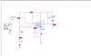
So i have this circuit (schema.png)
I have to change values from VIN(VPULSE) to get this result in simulator (zzz.png)
I really appreciate if you can help me with some values to get the right results , i'm trying from 1 hour and i can't. (I'm newbie so be gentle )
Thank you
So i have this circuit (schema.png)
I have to change values from VIN(VPULSE) to get this result in simulator (zzz.png)
I really appreciate if you can help me with some values to get the right results , i'm trying from 1 hour and i can't. (I'm newbie so be gentle )
Thank you