Continue to Site

Welcome to our site!

Electro Tech is an online community (with over 170,000 members) who enjoy talking about and building electronic circuits, projects and gadgets. To participate you need to register. Registration is free. Click here to register now.

  • Welcome to our site! Electro Tech is an online community (with over 170,000 members) who enjoy talking about and building electronic circuits, projects and gadgets. To participate you need to register. Registration is free. Click here to register now.

Help on reducing/removing inductance

Status
Not open for further replies.

zexclo

Member
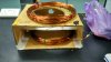
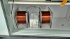
Hi, currently I working on a helmholtz coil, to generate a radio-frequency at the centre of the coil, a field strength of 1A to 2A is put into the coil, and the frequency ranges from 10Mhz to 50Mhz.

However, currently I am facing a problem where I believe the fields are not at the centre of the coil. The measured inductance of the coil is 4.87mH and resistance is 1.43 ohm.

Here comes my question...
1.From my reading, am I safe to say that the adding of capacitor to this circuit will "remove/cancel out" the inductance,and solve my problem of the "field not at the centre" of the coil?

2. Using LC circuit, given inductance is 4.87mh, and resistance is 1.43ohm. I have done some calculations.
with Frequency = 50Mhz.

where 50 * 10^6 = 1/ (2pie ( sqrt ( 4.87* 10^(-3)C )
my Capacitance value would be 2.0803 x 10^(-15)

currently, I am only able to find capacitor value of .1 x 10^(-12) F in the mkt.
To remove the inductance, do i really need to arrange 49 capacitor rated at .1 x 10^(-12) F in series?
(as I assume the number of capacitor arrange in series = x)
(
2.08 x 10^(-15) = 1 / ( x ( 1 / (1.01 * 10 ^(-12)) )
x = (0.1 * 10 ^ (-12)) / (2.08 * 10^ - 15)
x = 49
)

Am I wrong in any of my understanding and assumptions?
Is there any other alternatives to solving the problem of high inductance value and the field not in place?

Thanks in advance,for your kind assistance (Not exactly that bright in electronics)
 
Last edited:
You either have way too many turns on your coil, or you should be trying to resonate the one you describe at a few tens to hundreds of kHz.
 
1 mH = 1 milli-henry = 1e-3, not 1e-6
Right. So, if the coil really is 4.87 millihenries, then that's way too much inductance for frequencies around 50 MHz. The coil will be well above its self-resonant frequency. The current and voltage in the coil will form standing waves (or worse, traveling waves), and there is no possible way to have a uniform field.

At 50 MHz, the free space wavelength is 6 metres. If you want a uniform field, then the total amount of wire in your coil will have to be much less than the wavelength, at least by a factor of ten, and probably more. So, your coils would have to be wound with no more than 0.6 metres of wire. If that's not enough to give you the size of coil that you need, then you would have to use multiple coils, and feed them in parallel.
 
Last edited:
You either have way too many turns on your coil, or you should be trying to resonate the one you describe at a few tens to hundreds of kHz.

For the frequencies, I am unable to reduce the 50Mhz lower as that is the input value needed.

Right. So, if the coil really is 4.87 millihenries, then that's way too much inductance for frequencies around 50 MHz. The coil will be well above its self-resonant frequency. The current and voltage in the coil will form standing waves (or worse, traveling waves), and there is no possible way to have a uniform field.

At 50 MHz, the free space wavelength is 6 metres. If you want a uniform field, then the total amount of wire in your coil will have to be much less than the wavelength, at least by a factor of ten, and probably more. So, your coils would have to be wound with no more than 0.6 metres of wire. If that's not enough to give you the size of coil that you need, then you would have to use multiple coils, and feed them in parallel.

Yea, I believe that there is a strong standing(or travelling waves) as the strongest field strength is not at the centre of the coil, but at other location.

Can I understand that the only way to reduce the self-resonant frequency and the inductance value is only by reducing the number of coils?
Currently, a side of the coil has 74 turns, diameter of 20.5, total length is 48.82m.
 
Is there any other ways which I can prevent the self-resonance frequency? What will happen if I add capacitor to the circuit?
 
Is there any other ways which I can prevent the self-resonance frequency? What will happen if I add capacitor to the circuit?
A capacitor will reduce the frequency.

Now each turn of wire makes a capacitor to all other turns of wire. You have much capacitance you don't know about.

How big is the coil? The only ones I made are big enough to walk inside of.
-----edited------
You should tell us that you are trying to do.
 
Last edited:
Dont know how accurate this calc is for such a large coil.

sol.gif
 
Here is the resonance of the coil with four different capacitors, namely 10pF,100pF,1000pF and 10nF. Note that the self-resonance of the coil with no added capacitance is likely to be ~100kHz.

281.gif
 
Is there any other ways which I can prevent the self-resonance frequency? What will happen if I add capacitor to the circuit?
Adding capacitance won't help. It will lower the frequency where it resonates, making things worse. You want the self-resonant frequency to be as high as possible. At resonance, the the coil no longer acts like a simple inductor. It becomes a transmission line resonating at a frequency corresponding to a wavelength equal to twice the length of wire in the coil. That is, the coil becomes a halfwave resonator, and will have zero current flowing at the ends (current nodes) and maximum current flowing in the centre of the wire. Since the magnetic field is proportional to the current flow, you'll get an uneven field. There are no external components that you can add that will change what is going on in the coil.
 
A capacitor will reduce the frequency.

Now each turn of wire makes a capacitor to all other turns of wire. You have much capacitance you don't know about.

How big is the coil? The only ones I made are big enough to walk inside of.
-----edited------
You should tell us that you are trying to do.

I am trying to make a magnetic coil, to generate a field strength where the maximum strength is at the centre of the coil.
The input frequency is 50Mhz and 2 Ampere.
The length of my coil currently is 97.64m, which is adjustable (buy more or cut)

Currently, this is my coil, the distance between the two coils are 10.5cm (half the Diameter of the coil).

I admit I am newbie in electronics. From my peers, they are saying that adding of capacitors will help "remove" the inductance and help generate the strongest field strength at the centre of the coil.
 

Attachments

  • IMG_20151015_094654_HDR.jpg
    IMG_20151015_094654_HDR.jpg
    1.3 MB · Views: 234
Thank Mike for the useful site and link, have updated the information.
The coil is actually not that big as from the updated pic. LOL

Not sure if I am righ, as the design of my coil and the image seems different.
there is two coils, arranged in series,
with 74 turns in each coils,
the length of the coil is about 12 cm, and we are putting in around 2A.
The inductance is about 3mH.

Untitled.png
 
From my peers, they are saying that adding of capacitors will help "remove" the inductance and help generate the strongest field strength at the centre of the coil.
That is partly true. If you add capacitance in series it has a negative reactance which will cancel out the positive reactance of the coil, reducing the overall impedance of the circuit, and allowing more current to flow. However, your coil has too much wire in it as I explained earlier. And in addition, the coil will have very high self-capacitance, which at 50 MHz will mean that most of the current will bypass the coil anyway. I recommend that you replace your coils with single turn loops.
 
I recommend that you replace your coils with single turn loops.

By this, you meant that I should re-do my coil. Instead of the current coil, I should re-coil them into single turn, and this will help to reduce the impedance?
and should there is impedance, I can add capacitance in series to cancel the positive reactance of the coil?

If i re-coil into single loop, is it alright that the turns are still quite large at large at 140s, with around 70 per side?
 
By this, you meant that I should re-do my coil. Instead of the current coil, I should re-coil them into single turn, and this will help to reduce the impedance?
Yes.
and should there is impedance, I can add capacitance in series to cancel the positive reactance of the coil?
Yes, you can add capacitance, but the inductance will now be very low so it will be less important.
If i re-coil into single loop, is it alright that the turns are still quite large at large at 140s, with around 70 per side?
I don't understand what measurement units you are using. But from the photo it appears that you mean 140 mm. If so, then yes, it should be okay.

You'll want to use much larger diameter wire, or possibly copper tubing.
 
I don't understand what measurement units you are using. But from the photo it appears that you mean 140 mm. If so, then yes, it should be okay.

You'll want to use much larger diameter wire, or possibly copper tubing.

my bad, I meant that if its alright if the coils have large turns, 140 turns in total with 70 turns per side. But you seems to have answer the question where,if its single coil by the inductance should be low, hence the adding of the capacitance should help.

Hence, if I understand you correctly, if I manage to single coil like the image. and if the measured inductance is 1.34mh, I should be able to use a capacitor to cancel the positive reactance of the coil?
 

Attachments

  • IMG_20151015_120323_HDR.jpg
    IMG_20151015_120323_HDR.jpg
    1.5 MB · Views: 227
Your latest image still shows multi turn coils, not single turn loops. And 1.34mH is still much too high by a factor of about 1000. You don't want millihenries; you want microhenries.
 
IMG_20151015_153317_HDR.jpg
I am kinda confused. Hence, I drew this image.
By single turn loops, do you meant by number 1 or number 2? For the second picture, the coils are arrange in number 1, just that the coils are more closely packed together. I am assuming that single turn loops are actually number 1, and multi-turn loops are number 3.
 
Number 2.
At 50 MHz, 1 and 3 will have so much inductance and self capacitance that you won't be able to get any significant amount of current to pass through the wire, and therefore won't be able to generate any significant magnetic field.
 
Status
Not open for further replies.

Latest threads

Back
Top