Hi,
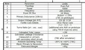
We got a planar txformer done for push-pull 24vin 32vout 300w 225khz, split sec.
They gave us a spec of 1.2uH (as attached) for pri:sec leakage L.
But over the phone have said its actually 100nH.
But do you think we are being pinickity to ask for the leakage L between both halves of the primary too? (ie short one primary half, and measure the inductance at the other primary half.)
Or is it just taken as wrote that Planar designers make this vanishingly small.?
Why do you think they did not give this inter-primary leakage figure? (attached only shows pri:sec leakage L)...i mean, they know its for a pushpull use.