Continue to Site

Welcome to our site!

Electro Tech is an online community (with over 170,000 members) who enjoy talking about and building electronic circuits, projects and gadgets. To participate you need to register. Registration is free. Click here to register now.

  • Welcome to our site! Electro Tech is an online community (with over 170,000 members) who enjoy talking about and building electronic circuits, projects and gadgets. To participate you need to register. Registration is free. Click here to register now.

Help on input-output circuit

Status
Not open for further replies.

Futterama

Member
Hello forum,

First, I must admit, I didn't do a search on the forum on my topic since I just don't have a clue for a keyword...

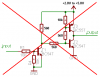
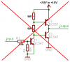
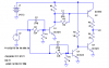
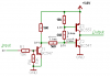
Now, my problem is this: I want to take a digital signal 0-3V and convert it to 0-5V or 0-2V (by changing the supply from 5V to 2V) using transistors (I can't really find an IC, and I only need 2 input/outputs and then a 14pin IC is too space demanding on my board).

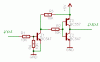
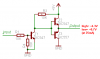
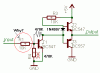
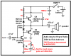
I have come up with the circuit shown below.

It needs to be able to handle a bit of current, like 25mA on the output (sink/source).

The problem is, it shorts the supply.

What am I doing wrong?

If you by chance know a common IC with 2 inputs/outputs with a voltage range of 2-5V, please let me know. Thanks.

Regards,
Futterama
 

Attachments

  • in-out.gif
    in-out.gif
    4.2 KB · Views: 748
Nigel Goodwin said:
You have the two bases joined together, so both transistors are permanently ON.
Hi Nigel, thanks for your reply.

Why would this happen when the one transistor is NPN (BC547) and the other is PNP (BC557)?

As far as I know, the base of BC557 should be below 4.3V to turn the transistor ON, and the base of BC547 should be above 0.7V to turn that transistor ON.
So when the bases are 0V, only the BC557 will be ON, and when the bases are 5V only the BC547 will be ON.

What do I misunderstand about transistors?

Regards,
Futterama
 
Futterama said:
Nigel Goodwin said:
You have the two bases joined together, so both transistors are permanently ON.
Hi Nigel, thanks for your reply.

Why would this happen when the one transistor is NPN (BC547) and the other is PNP (BC557)?

As far as I know, the base of BC557 should be below 4.3V to turn the transistor ON, and the base of BC547 should be above 0.7V to turn that transistor ON.
So when the bases are 0V, only the BC557 will be ON, and when the bases are 5V only the BC547 will be ON.

What do I misunderstand about transistors?

Regards,
Futterama
Bipolar transistors are basically current-controlled devices. You seem to think they are voltage-controlled, and that the base-emitter junction can handle any voltage you put across it. This is not the case. The base -emitter junction is a diode. When you connect the bases together, you have connected two diodes, in series, across your power supply. This will either burn out one or both of your transistors, or it will cause your power supply voltage to drop.
 
audioguru!!!

I think your arrangement will still heat transistors :shock: :shock: :shock:

It is very important that the diode is used to lower distortion, and prevent problems from occuring.

you need the (hand drawn) 470K resistor between base and collector so that auto biasing can be used Your (crossed-out) 10K resistor should be replaced with a 470K resistor to create balance. A low resistor may increase bandwidth, but lowers gain, and a high resistor could allow the coupling capacitor (from some audio output) to delay the correct audio, if the capacitor is too large.

and the circled resistor, why is it there, and why is it that large of a value? All it does is attenuate the input signal (reduce volume).

and for the transistors, I think the reason why your original transistor arrangement is wrong is because current flows from collector to emitter when the base is at the right polarity, and enough current and voltage is connected to the base.

In the simplest terms, your original arrangement allowed current to go through the 10K resistor, and touch the NPN's base. Because the base is +ve, which NPN expects, and because it has enough current and voltage, the emitter turns on, and therefore you almost have a completely short circuit. What saved your parts was the 10K resistor.
 

Attachments

  • ckt_497.gif
    ckt_497.gif
    4.7 KB · Views: 699
mstechca said:
audioguru!!!

I think your arrangement will still heat transistors :shock: :shock: :shock:
It is a digital switch, not an audio amplifier!

Since you are thinking about an audio amplifier:

It is very important that the diode is used to lower distortion, and prevent problems from occuring.
No. You need two diodes in series to cancel the two base-emitter junctions, plus emitter resistors for the transistors.

you need the (hand drawn) 470K resistor between base and collector so that auto biasing can be used
You might as well have your 470k resistor connected to the output for overall negative feedback. If it oscillates at a few MHz then add a 22pF cap where your 470k resistor is located.

Your (crossed-out) 10K resistor should be replaced with a 470K resistor to create balance.
No. It isn't needed. An emitter resistor should be added to the 1st transistor to reduce its distortion.

the circled resistor, why is it there, and why is it that large of a value? All it does is attenuate the input signal (reduce volume).
It raises the amp's input impedance and allows the negative feedback to work.
Did you forget our discussion about this simple amp a few months ago? Look at my attachment.

and for the transistors, I think the reason why your original transistor arrangement is wrong is because current flows from collector to emitter when the base is at the right polarity, and enough current and voltage is connected to the base.

In the simplest terms, your original arrangement allowed current to go through the 10K resistor, and touch the NPN's base. Because the base is +ve, which NPN expects, and because it has enough current and voltage, the emitter turns on, and therefore you almost have a completely short circuit. What saved your parts was the 10K resistor.
No. The positive battery current flows through the emitter-base diode of the PNP transistor directly through the base-emitter diode of the NPN transistor. The two diodes in series will try to drag the battery voltage down to about 1.4V with very high current.
 

Attachments

  • simple_amp.png
    simple_amp.png
    14.5 KB · Views: 674
I know. The value of the 390k resistor is too high. Maybe 39k would work better, then the input resistor should also be reduced and the input capacitor increased.

The push-pull transistors should have emitter resistors.
The entire circuit should be an LM386 IC. :lol:
 
I only need 2 input/outputs and then a 14pin IC is too space demanding on my board

By the time you complete the circuit with discrete transistors, it will occupy more space than a 14-pin IC.

An open collector LM393 or LMV393 can be used as such a level shifter. If that part does not suit you, there are plenty of low voltage parts to chose from in the national semiconductor website.

**broken link removed**
 
Hey Ron,
This circuit should swing a 2V to 5V 25mA output pretty well. Its 560 ohm resistors will eat a fair amount of current, and the transistors will fry if the input switches slowly.
 

Attachments

  • in-out_again.png
    in-out_again.png
    7.1 KB · Views: 640
audioguru said:
I know. The value of the 390k resistor is too high. Maybe 39k would work better, then the input resistor should also be reduced and the input capacitor increased.

The push-pull transistors should have emitter resistors.
The entire circuit should be an LM386 IC. :lol:
I was actually talking about the push-pull emitter follower circuit that you originally posted.
 
motion said:
An open collector LM393 or LMV393 can be used as such a level shifter.
The LM393 is low-power, which also means that it has low output current. Its min output current is only 4mA, with a terrible max saturation voltage of a whopping 700mV. :lol:
 
audioguru said:
Hey Ron,
This circuit should swing a 2V to 5V 25mA output pretty well. Its 560 ohm resistors will eat a fair amount of current, and the transistors will fry if the input switches slowly.
Scrooge, I think both output transistors are on, in either input state. Below is a crude analysis of currents for Vin=3V, VCC=5V. As I said, I think you will find that the same is true if you analyze it for Vin=0V.

Below is my best shot (at least for now). This runs OK with on or off pulse widths of less than a microsecond (or wider, of course). If our OP wants to only run slow, he can omit the capacitors. It will work even faster with transistors designed for fast switching (e.g. 2N2369, 2N5771), but resistor and capacitor values would all have to be re-optimized.
 

Attachments

  • push-pull.png
    push-pull.png
    9.5 KB · Views: 703
  • in-out_yet_again.png
    in-out_yet_again.png
    6.1 KB · Views: 718
Thank you all for your replies.

I can see, it's more complicated than I thought.

Ron H said:
Bipolar transistors are basically current-controlled devices. You seem to think they are voltage-controlled, and that the base-emitter junction can handle any voltage you put across it. This is not the case.

It's true, I'm not thinking of the transistors right. I'll read up on that.

The R1 input transistor is for protecting the source of the input signal (PC LPT port). Perhaps I should read on calculating the resistors cause I need the T1 because the LPT output can vary from PC to PC and from desktop to laptop - and to "convert" the 3V signal to 5V or 2V.

Originally I wanted to use a 74HC04 instead of the 2 transistors (4 in total because of 2 inputs/outputs). And I looked at the space demands, and they are actually close to be the same for the IC and the 4 transistors + resistors even though I only use 2 inputs/outpust of the 74HC04.

Conclusion: I'll use the 74HC04 and forget about the transistors.

Thanks to everyone for the replies 8)

Regards,
Futterama
 
Status
Not open for further replies.

Latest threads

Back
Top