Butlerian Electrician
New Member
Good day internet humans,
I am pretty new to the world of diy electonics, and am in the process of putting together a DIY portable computer monitor built from an lcd panel from an old laptop and a driver circuit board I got off of ebay (https://www.ebay.com/itm/153738236225). My first idea was to power it using a usb-c power deliver trigger circuit (ZY12PDN) and a 18w powerbank that supported 12v usb-c power mode, as the lcd control board requires 12 volts. This arrangement works perfectly and powers the portable monitor fine, however, I can now only power the monitor from the powerbank. When I purchased the powerbank, I made sure it had passthrough charging, that way I could simultaneously charge the battery and supply the required 12v to the control board, but when the powerbank goes into passthrough charging mode, it aborts the 12v PD mode, and goes into a standard 5v mode. This means I can only use the monitor when the powerbank is charged, and must stop using the monitor while the powerbank is recharged. While using the monitor in this arrangement, I monitored the power draw from the powerbank, and it never surpassed 6w. Because of this, I figured I could just change the power delivery circuit to always operate at 5v, and just put a step-up boost module (https://www.ebay.de/itm/153023571670?hash=item23a0ea66d6:g:xJAAAOSw6qheafHX) between the PD trigger and the control board, and tune the dc-dc step up module to output 12v. I realize this totally negates the functionality of the PD trigger, but I figured I already bought it, and it functions as a usb-c inlet, and maybe could even increase efficiency when operating at 12v in battery mode.
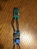
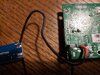
After soldering everything together in this configuration and plugging power in, the dc-dc step up converter makes a kind of brief clicking noise before the PD trigger just turns off, and I do not know why. the 18w battery bank should supply more than enough amps, as in all sorts of testing at maximum screen brightness in a number of scenarios, I could never get the control board to draw more than 5.6w. The problem persists even when using an 18w usb-c wall charger. I have attached a few pics showing the configuration. A few wires have been de-soldered while I've been troubleshooting, but it should be clear where they were attached. (please excuse my awful soldering abilities). If anyone can inform me why I am failing so hard, or what I can do to make this work, I would be very grateful for your help, and even just for reading this crazy long entry.
Cheers from a circuitry noob!
I am pretty new to the world of diy electonics, and am in the process of putting together a DIY portable computer monitor built from an lcd panel from an old laptop and a driver circuit board I got off of ebay (https://www.ebay.com/itm/153738236225). My first idea was to power it using a usb-c power deliver trigger circuit (ZY12PDN) and a 18w powerbank that supported 12v usb-c power mode, as the lcd control board requires 12 volts. This arrangement works perfectly and powers the portable monitor fine, however, I can now only power the monitor from the powerbank. When I purchased the powerbank, I made sure it had passthrough charging, that way I could simultaneously charge the battery and supply the required 12v to the control board, but when the powerbank goes into passthrough charging mode, it aborts the 12v PD mode, and goes into a standard 5v mode. This means I can only use the monitor when the powerbank is charged, and must stop using the monitor while the powerbank is recharged. While using the monitor in this arrangement, I monitored the power draw from the powerbank, and it never surpassed 6w. Because of this, I figured I could just change the power delivery circuit to always operate at 5v, and just put a step-up boost module (https://www.ebay.de/itm/153023571670?hash=item23a0ea66d6:g:xJAAAOSw6qheafHX) between the PD trigger and the control board, and tune the dc-dc step up module to output 12v. I realize this totally negates the functionality of the PD trigger, but I figured I already bought it, and it functions as a usb-c inlet, and maybe could even increase efficiency when operating at 12v in battery mode.
After soldering everything together in this configuration and plugging power in, the dc-dc step up converter makes a kind of brief clicking noise before the PD trigger just turns off, and I do not know why. the 18w battery bank should supply more than enough amps, as in all sorts of testing at maximum screen brightness in a number of scenarios, I could never get the control board to draw more than 5.6w. The problem persists even when using an 18w usb-c wall charger. I have attached a few pics showing the configuration. A few wires have been de-soldered while I've been troubleshooting, but it should be clear where they were attached. (please excuse my awful soldering abilities). If anyone can inform me why I am failing so hard, or what I can do to make this work, I would be very grateful for your help, and even just for reading this crazy long entry.
Cheers from a circuitry noob!