harrythedick
New Member
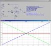
V IN FREQ OUT
2.5V 1khz
3.0V 1.75khz
3.5V 3.12khz
4.0 6.26khz
5.0V 10khz
6.0V 12.5khz
9.0V 20.8khz
sorry guys but my questions like this. the output from my op amp would be fed into a vco which would convert the voltage into the freq according to the above table. is there anything that i could do which would give me an inverted result? the results i wanna achieve is something like this( the op amp is used to amplify the voltage give from a ultrasonic sensor)
V IN FREQ OUT
2.5V 20.8khz
3.0V 12.5khz
3.5V 10khz
4.0 6.26khz
5.0V 3.12khz
6.0V 1.75khz
9.0V 1khz
thanks!!!!
Last edited: