Continue to Site

Welcome to our site!

Electro Tech is an online community (with over 170,000 members) who enjoy talking about and building electronic circuits, projects and gadgets. To participate you need to register. Registration is free. Click here to register now.

  • Welcome to our site! Electro Tech is an online community (with over 170,000 members) who enjoy talking about and building electronic circuits, projects and gadgets. To participate you need to register. Registration is free. Click here to register now.

Help needed Yamaha YST-SW800 faults

Status
Not open for further replies.

samurai_x47

New Member
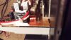
Hi, in short I have this sub X2, 1 went bad a year or so ago, powers up but has no sound, but I bought another quite cheap. However just now it was ok, I left the room and heard a loud pop, as if the relay shut off louder than normal. Now there is no sound at all and the relay will not switch on as the same for the other sub.

Both fuses are ok still in both of them, just do not know what to look for, I guess swollen caps? And burnt, dark patches?

Any help would be appreciated...
 
Swollen capacitors (or low-ESR ones) are mostly associated with switch-mode power supplies, does it use a switch-mode PSU?.

The loud POP, and now not coming on, sounds more like an amplifier failure.
 
Hi Nigel, I was hoping it wasn't that. I believe it is a switching mode PSU. Attached a few pictures of it.

The fuse didn't blow, but, should I now check all the caps, transistors just incase? Nothing looks swollen.

I read if the base is defective and not the emitter (if they are bad) then the voltage backup through the circuit is very bad...
 

Attachments

  • IMAG1224 (wecompress.com).jpg
    IMAG1224 (wecompress.com).jpg
    1.3 MB · Views: 451
  • IMAG1227 (wecompress.com).jpg
    IMAG1227 (wecompress.com).jpg
    893.6 KB · Views: 386
  • IMAG1229 (wecompress.com).jpg
    IMAG1229 (wecompress.com).jpg
    771.4 KB · Views: 792
Randomly checking components isn't a good way to repair anything, although it's an easy way with SMPSU's to check the electrolytics before you do anything else. However, you MUST use an ESR meter (with the unit unpowered), or a scope (with the unit powered).

But easiest thing to do first is check the voltages in the amplifier outputs - assuming it's spilt supply? (which is likely) then there should be high positive on one rail, high negative on the other rail, and the output to the speakers (before the relay) should be zero or very close to it. The relay is there mainly to protect the speakers in case of amplifier failure, where the output of the amplifier will probably have a high DC voltage on it (which is death to a speaker).
 
Ok, I'll measure that then. Where do I put the probes on my meter on the output stage? And I switch it to measure voltage I presume.
 
Yes you need it set to DC voltage, and probably set to 200V or so (you're probably looking at +/-50-70V).

As for where, do you have the schematic for the amplifier?.
 
I would do so, you can't do much without a circuit.
Thing is, I'm only a amateur, no qualifications in this area. I know how to tell f the simple things like a cap is bad (have a cap meter and a multi meter) I'm thinking I may have to send them off to a professional :( 
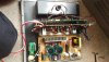
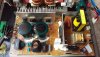
I only understand so much of a service manual circuit diagram.
 
P.S. I did have a pro take a look at my 1st back plate, he repaired the power board but was not willing to go any further as he stated the design of the board was very bad, thus not worth repairing as he'd have to redesign some of it to be a reliable circuit.

I'm not sure what to do, but I'll still have a look at the components.
 
I've just downloaded the service manual, there's an inductor (L5) with a resistor (R171) in parallel that feeds the speaker (before the relay), those should be simple to locate - check the DC voltage on them (from chassis), with the amp turned ON. It should be zero volts, or very close - anything more than a few 100mV shows the amp is blown. DC coupled amps aren't trivial, the slightest mistake is like a chain of dominoes, and if you don't replace all faulty parts, then as soon as you switch it on it all blows again.
 
I can't get to the resistor in circuit to measure it without having to take the board out... If I do, the transistors wont be touching the thermal paste on the back plate.
 
In picture 1230 the inductor looks easily accessible, chassis is any of the metal chassis work (which is 0V), the metalwork immediately below the inductor would be fine.
 
Status
Not open for further replies.

Latest threads

New Articles From Microcontroller Tips

Back
Top