Continue to Site

Welcome to our site!

Electro Tech is an online community (with over 170,000 members) who enjoy talking about and building electronic circuits, projects and gadgets. To participate you need to register. Registration is free. Click here to register now.

  • Welcome to our site! Electro Tech is an online community (with over 170,000 members) who enjoy talking about and building electronic circuits, projects and gadgets. To participate you need to register. Registration is free. Click here to register now.

Help Needed with SCUBA Light Switch Circuit

Status
Not open for further replies.

Klemheist

New Member
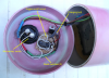
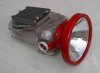
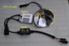
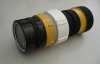
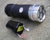
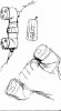
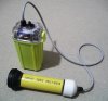
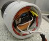
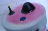
I am building a SCUBA torch using a piezo switch (these work well underwater) and two LED heads.
The sequence I am after is;
First press...LED 1 on,
Second press... both LED 1 & 2 on.
Third press...both off.


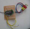
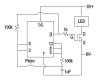
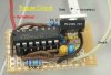
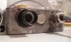
The circuit in my current torch has only one LED and uses a 555timer to toggle the LED on/off via the piezo. The 555 output operates a FET allowing 1amp to flow.

Do I need to source a programmed chip or can this circuit be made using ordinary non-programmable parts?

Regards

Mac
 
The ckt can be made of ordinary non-programmed parts. You're describing the operation of a simple binary counter. Look up binary counter circuits before going thru the complexity of using a programmed solution.


BTW, I'm a diver too!
 
Last edited:
SCUBA Torch Ongoing

Brownout
Thanks for that,
I thought as much but my expertise extends to soldering and sourcing parts, not designing the actual circuit.

Here's a couple of pictures of two existing torches we've made using MR16 size tripple CREE XR-E LED's by Terralux, in a converted Maglite head. One uses a piezo and the other a magnetic reed swich array. Both with the same 556 toggle circuit.

Batteries are 2-cells of 4*18650 Li-ion's + protection circuit. About 5Ah of capacity on a 3watt draw. Doubling this should still give enough for two dives before needing top re-open for re-charge/change.

If I can get something as compact as the existing switch circuit arrangement that will save on unwanted buoyancy.

Any help on the circuit detail most appreciated.

Cheers
Klem
 

Attachments

  • Blinder MkII.jpg
    Blinder MkII.jpg
    58.8 KB · Views: 679
  • torch and battery.jpg
    torch and battery.jpg
    59.2 KB · Views: 889
  • concept torch.jpg
    concept torch.jpg
    32.7 KB · Views: 974
Hi klemheist,

here is a circuit not quite to your desire, but may be you'll like it.

The functions are:

LED1 - ON, LED2 - ON, LED1 + LED2 - ON, ALL OFF

I hope it fits into your enclosure without changes to the design.

R5 and R6 are calculated for white LEDs with 3.5V forward voltage and 20mA forward current.

More info on the attached files.

Boncuk
 

Attachments

  • DUO-TOGGLE-SWITCH-SCH.pdf
    28.3 KB · Views: 641
  • DUO-TOGGLE-SWITCH-BRD.pdf
    14.4 KB · Views: 450
Last edited:
Just in case the PCB is too large, here is an SMD-version with dimensions 0.91875X0.65inches.

Boncuk
 

Attachments

  • DUO-TOGGLE-SWITCH-SMD-BRD.pdf
    14.8 KB · Views: 425
Dive torch ongoing

Boncuk,

Thanks for that, this is exactly what I am after.

No, I don't think space will be a problem. It looks a similar number of components to our existing single-LED toggle circuits (see photo).

On that. Do you think I can take the two outputs from your 4027 Flip Flop and instead of them activating transistors have them activate a FET instead?

Our current switch circuit uses a logic FET like the IRLZ34N to power these 3Watt LEDs. I was advised that logic FETs allow them to open completely when you want them too, with minimal resitance and copes well with the high current.

One more question. I am unsure what the acronyms at the top of your circuit mean; "S1-I, S1-O" and the four to the top right, "D2, D1". I assume they mean Switch One Input and Output but don't know the others. Are these necessary in my case?

Also, unsure what the line between the 6V symbol and Ground is ('IC 1P').


Klem
 

Attachments

  • Toggle-circuit-revised.jpg
    Toggle-circuit-revised.jpg
    22.4 KB · Views: 1,975
  • Toggle Circuit Photo A.jpg
    Toggle Circuit Photo A.jpg
    63.8 KB · Views: 1,506
Boncuk,

Thanks also for the circuit design. As you can see I buy one of these project boards and tyr and figure out how to solder wires connecting it all up.

I know I should get into PCB building and etching but have never really found the time. Any starter advice here would be welcome

Klem
 
How much pressure is needed to activate your touch switch? How deep do you plan on diving to? 32 feet is 1 ATM.
 
Hi Klem,

since the switch and the LEDs are not located on the PCB the labels and solder pads are used to connect the switch and the LEDs.

S1-I and S1-O are connected to the switch. In the schematic both, switch and LEDs are dummies for better understanding.

+D1 and D1- as well as +D2 and D2- are connected to LED1 and LED2 respectively. (+ = anode, - = cathode)

IC1 P (IC1 Power) represents the supply pins of IC1, which can be identified looking at the pin numbers (8 for ground and 16 for VDD).

I will redesign the circuit for power MosFets.

According to the schematic you posted that circuit allows only one LED to be switched.

Boncuk
 
SCUBA Toggle Switch circuit ongoing

Boncuk,

OK, understood on the solder pads....makes perfect sense now.

Yes, our existing toggle circuit is an on/off for one LED only, but necessary when using a non-mechanical momentary switch like a piezo. I included the photo to show the size and where we're at as far as expertise (or lack of it!) is concerned.

Klem
 
Mikebits,

Yes, pressure is an issue with torch switches underwater and you are right to point this out. You need a switch that handles up to 5 atmospheres. From 1 atmosphere at the surface to at least the limit of diving on air...50metres, 6 atmospheres.

As you allude, diving is a harsh and unforgiving environment on electrical equipment. normal mechanical toggle switches work with waterproof rubber boots, but they are high profile and prone to getting knocked or the rubber pierced.

Commercial torches use mechanical switches going through a waterproof O ring to the inside

Press toggle on/off switches are useless as they become permanently compressed underwater with the pressure. So a reverse clicky toggle never goes on and a forward clicky toggle is constantly on.

Another method is to use a magnetic reed switch, either with the magnet applied for the entire dive or use a toggle circuit like in this thread with a momentary swipe. obviously normal reed switches are amps limited so you have to have some sort of relay system happening for the high amps needed. reeds are fragile to the knocks and bumps so be careful but they do help with the 'hull integrity' and are low profile.

Finally there is the more expensive piezo option with a toggle circuit. We've dived to 45 using piezo switches with no problems. As the ambient pressure increases and decreases on the piezo it is gradual enough that it doesn't respond like an intended activation. It works just as well at 45metres as it does on the surface.

attached are photos of different switches we have used. Some with more success than others.

It's a constant journey of discovery

Cheers
klem
 

Attachments

  • complete.jpg
    complete.jpg
    32 KB · Views: 569
  • new array.jpg
    new array.jpg
    38.9 KB · Views: 545
  • Punisher II Upgrade.jpg
    Punisher II Upgrade.jpg
    87.7 KB · Views: 604
  • IMGP4064.jpg
    IMGP4064.jpg
    64.1 KB · Views: 435
  • open.jpg
    open.jpg
    31.7 KB · Views: 408
  • IMGP0767.png
    IMGP0767.png
    707.7 KB · Views: 633
Hi Klem,

I've changed the design to use two IRLZ34 transistors.

Making the PCB using SMD components the board size will increase considerably since the transistors have D2Pak packages which require quite some space on the PCB even if one is mounted on the solder side.

Using discrete wired parts the PCB dimensions have slightly increased in length only. The overall height above PCB is approximately 15mm due to the TO262 packages of the transistors.

The TerraLux CREE XR-E can be operated at 1000mA max. The design stays well below the max value with 978.72mA at UB +6V (not considering RDSON of the MosFets) For less current change the values of R5 through R8.

Also, I don't understand the problem concerning push button operation in a submerged torch. You can use any pushbutton with an operating pin having at least 5mm length. Use the latex cover (102 bubbles) of a spill proof PC-keyboard and mount the pushbutton underneath adding a spring strong enough for the water depth you are planning for. (See attached sketch). For safer operation you might add a retainer ring at the top of the operating pin.

Also attached are thre PDF files of the circuit. If you are going to make PCBs you are welcome to receive the Eagle files via email.

Regards

Boncuk
 

Attachments

  • TORCH-BUTTON.gif
    TORCH-BUTTON.gif
    10.2 KB · Views: 633
  • DUO-TOGGLE-SWITCH1-SCH.pdf
    35.3 KB · Views: 428
  • DUO-TOGGLE-SWITCH1-BRD.pdf
    16.3 KB · Views: 408
  • DUO-TOGGLE-SWITCH1-SILK.pdf
    13.2 KB · Views: 412
Last edited:
Dual LED SCUBA Switching Circuit

Hi Boncuk,

Thanks again for that.

I've printed out all three files you sent and stared at them for the last 45 minutes. I see how you have rotated the larger FETs to save space and board width, plus thickened the tracks in parts...no wasted space...very nice!

It's not much larger than the earlier BC547 board at all. This is terrific for when we start looking to fit it inside the 50mm tube.

One question. I see Pin 8 on the IC4027 is connected to Ground on the circuit-board diagram, however is not shown on the main circuit diagram. Should this be the case, or left unused like Pin 15.

With your push-button switch query, you are of course correct, in that they can work underwater with the right amount of stiffness in the waterproof boot. Or as you allude the height is longer than the diameter (pressure from the sides more than pressure from top). This photo I showed earlier is a 'marine' momentary starter button, used in conjunction with a toggle circuit. It's the big black rubber button top-right. I remember diving to 20 metres with this design and the switch remained uncompressed by ambient pressure until you activated it. What didn't work however was the permanent seal arrangement. It had a couple of gelcel 12V battery's encased inside a 100mm PVC pipe with no access ports to aid waterproofing. Battery re-charging was via 2 brass bolts (one seen in the photo). These were kept from salt-water short-circuiting by a reed switch (also seen in photo).

Trouble is, the gelcel batteries didn't like being constantly deep-cycle drained and eventually they wore out, and on opening the terminals were all corroded and the reed switch semi-fused by high-amp charging exceeding it's rating. It was about to break down from any of those reasons but the battery was first. It was an early design...but, the switch did work fine.

These marine switches are fairly cheap also, and the rubber bomb-proof.

Cheers

Klem
 

Attachments

  • IMGP0764.png
    IMGP0764.png
    757.1 KB · Views: 689
  • IMGP0767.png
    IMGP0767.png
    707.7 KB · Views: 418
Hi Klem,

first off I wonder why you didn't mention pin16 (VDD) of the HEF4027. :) Together with pin8 it makes the power supply for that IC.

The power supply is the first item in the schematic on the left labelled 'IC1 P', meaning IC1 Power.

Pin15 is not connected on purpose since it's logic level is opposite of pin14's level, meaning if pin14 is high pin15 is low and vice versa.

By the number of experiments you have done so far I guess you'd be better off making an underwater floodlight of acrylic glass with the battery (SLA 6V/5.7Ah) and everything else encapsuled to make it 100% waterproof and deep sea going.

Acrylic glass is easy to handle and can be glued using the kind of glue camper manufacturers do. Basically it is acetone with a an additive of arsenic.

Using acrylic with 10mm thickness you will be able to dive to 100m without breaking it (provided the enclosure is not too big, or slightly arc the material applying heat) To make it safe you might equalize the inside pressure close to ambient pressure by inflating a baloon inside. (just the opposite of aircraft pressurization)

Further you can drill 'threaded sack holes' into it to mount any fixture inside.

In the meanwhile I have thought about the SMD-version, since the wired version is considerably high requiring lots of space.

The newly designed SMD-version has dimensions of 1.35X0.7625inches, using power MosFets type ZXMN05B14 (Zetex semiconductors), and available at Mouser for 31Cent each.

Even the IRLZ34 as D2Pak is 2,000% overkill for the load you intend to drive.

The mentioned transistor can drive loads up to 3.2A (still 320% overkill) :D and is available with an SOT23 package.

Kind regards

Boncuk
 
SCUBA switch

Boncuk,

Yes, Pin 8/16, power points... I see it now. Understood.

We do use Perspex (acrylic) lenses.

Perpsex has slightly higher light transferability than Lexan (polycarbonate). Glass, even tempered glass is too brittle for pressure diving. I can buy Perspex sheets for $20AU from our local glaziers.

Initially we used thick 6mm tempered glass, but after a flooding at 20M when one cracked we've gone to Perspex for the strength and flex. The only drawback is it's prone to melting or browning/burning if it gets too hot. For this reason we try not to turn on the big HIDs until we get underwater

We use different torches for different diving.

Night diving is the most critical. We carry two each. A main 35Watt HID for long-range focussed light, and a mask mounted LED for reading console instruments and working close.

Daytime diving we carry one light only...The larger LEDs I have been talking about, for compact under-ledge/cave illumination.

The photo is my 35W HID night torch, which has a 100mm diameter 10mm thick Perspex lens. Powered by two 5Ah 18650 Li-ion packs (12 batteries), at 3.5A gives 120mins-140mins (depending on battery quality) continuous light of about 2,500+ lumens, 5,000K light colour. Reflector is collimated so it's a true spotlight. The ballast is mounted outside the waterproof Otterbox where the water can cool it (it gets hot). The igniter is inside. Essentially these HIDs are sold as replacement vehicle headlights.

LED's are about 500 lumens, but far more compact. For the LED's, using an old Maglite torch using 10mm perspex is a bit too thick for the available bezel thread. We cut a 50mm disk and spin it in a lathe to cut a 'step'. The 10mm lens at the edge becomes a more usable 5mm. At 50mm diameter there is less surface area to flex under pressure so we are less concerned with catastrophic failure than the larger lights.

We try for around 5000+K colour temperature. This 'white' light is far more natural underwater than the 'dirty' yellow that incandescents give (around 3,500K).

I'm heading into RS Components to pick up the 4027's tomorrow. It may take a while as I need to order another LED head from the States. I'll post photos of the torch build as I go.

Cheers

Klem
 

Attachments

  • Punisher II Upgrade.jpg
    Punisher II Upgrade.jpg
    87.7 KB · Views: 480
  • IMGP4053.jpg
    IMGP4053.jpg
    62.6 KB · Views: 459
  • IMGP4235.JPG
    IMGP4235.JPG
    245 KB · Views: 411
Glass under pressure

Guys,

You were interested in the unforgiving nature of salt-water under pressure, so I tracked down this page;

**broken link removed**

It's a photo sequence on another blog of what happened to an earlier design of SCUBA torch

The 6mm tempered glass lasted until about 20 meters depth and then broke. That was when we started using Perspex.

DIY underwater torches...an expensive hobby

Klem
(Boncuk, RS stuffed up the order and so I'm still waiting for the FETs).
 
Test circuit made

Boncuk,

Still waiting on the FET's so I've built a test circuit in the meantime with your circuit. It works prefectly.

I applied 8V and measured the voltage straight off the 470 resistors and got the following toggle sequence;

1. Both on (8V)
2. Both Off
3. A only
4. B only

Terrific!

I'll post again later when the torch is assembled

Cheers

Klem
 

Attachments

  • dual JK.jpg
    dual JK.jpg
    46.3 KB · Views: 432
Hi Klem,

from my understanding it doesn't work perfectly yet.

I added a power up reset cap (resistor was already present) and now the sequence is as I planned:

1. all off
2. LED1 on
3. LED2 on
4. LED1 and 2 on
5. all off (again)

Please check the schematic and locate C3 (1µF electrolytic cap) connected between V+ and the clock input of IC1A.

This way the circuit is reset upon power up with no LED lit.

C3 offers an additional feature, since it limits the pushbutton trigger intervals with pauses of 400 to 500ms. (might be useful when trying to blind a shark, not inadvertantly switching off all LEDs in panic :) )

With this IC you won't need a power switch (main switch) for the battery. When no LED is switched on the circuit draws 120nA of current. When powering the circuit up initially the current flow is about 5mA for 1/2 second.

The PCB has become 0.1inch longer than the preceeding one.

Regards

Boncuk
 

Attachments

  • DUO-TOGGLE-SWITCH-SCH.pdf
    36 KB · Views: 351
1uF

Boncuk,

OK I'll give that a go

Nearest I have on hand at home is a 16V 10uF Electrolytic so I'll run by the store Monday

I can see the utility of not having the torch coming immediately on when you attach your battery pack. Saves immediately pressing the switch to turn it off.

Klem
 
Status
Not open for further replies.

Latest threads

New Articles From Microcontroller Tips

Back
Top