James12345
New Member
Hey folks,
Just created an account here to ask some advice since i have a somewhat similar scenario..
But really all i need to ask is in regards to 555 timers...
I'm just trying to get the darn thing to put out a one shot trigger. I'm using it within a 3PDT switch to run the 4017 sequence. The other two pulls do other things. My concept is just to have a separate 555 dedicated to putting out a trigger from a button press, which hits the reset on the 4017. Via other circuitry the sequence starts at the same time, so this all serves as a nice musical way to have control over the stop and start of the whole cycle, and having it start exactly at the begging when hitting start.
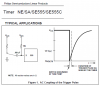
Problem is, I have a weird way of getting the 555 to make the necessary pulse. I'm basically using this.. **broken link removed****broken link removed**
It's designed so that the pulse only lasts the specified length no matter how long the momentary button happens to be pressed. This is exactly what i need, rather than needing to press and release the button a nanosecond") And i DO have it working, however i can only get it working when i simply switch on and off the actual +5 rail itself. This seems to do the trick.. on the scope, the pulse is exactly what i specify with the "Ra" and "C" above. Looks great. But, this is not how the circuit above is laid out. I've tried redoing and triple checking the above circuit, and never got it to send a pulse other than when i just powered the darn thing up. Nothing whatsoever showing up on scope. Spent hours just making sure it was perfect. So, i relocated the momentary switch to be the main power switch for the IC and just jump'd the spot where the momentary used to be in the schematic above.
And i DO have it working, however i can only get it working when i simply switch on and off the actual +5 rail itself. This seems to do the trick.. on the scope, the pulse is exactly what i specify with the "Ra" and "C" above. Looks great. But, this is not how the circuit above is laid out. I've tried redoing and triple checking the above circuit, and never got it to send a pulse other than when i just powered the darn thing up. Nothing whatsoever showing up on scope. Spent hours just making sure it was perfect. So, i relocated the momentary switch to be the main power switch for the IC and just jump'd the spot where the momentary used to be in the schematic above.
Any thoughts on using this method? My greatest concern is propagation time for when turning the whole 555 on... what will it be? In my final design, I need the pulse to last around 125 uSec so that it doesn't overlap past clock pulse #2's rising slope. I am designing to have a max frequency of the pulse clock coming out of the main 555 (not this one) as around 4K hz. As a reference, this means that instead of my pulse needing to last less than 1 millisecond (0.001) for a 1 kHz rate, i need it to first be 4 times shorter (0.000250) but as a safety just half that to be (0.000125). That is 125uS or 125,000 nanoseconds.
I'm pretty sure that's a fine range of operation for a 555 making a pulse, but powering it up first too? And is there a delay first, and then the pulse occurs?
Or, how can i get the above circuit working? I'm powering it with +5VDC. I've separated it completely from the rest of my circuit, and recreated it exactly as above, a few times over. I get nothing on the output with that circuit. As an easier test to measure, I've been using a .1uF cap and a 1M resistor. This gives a nice clear 100mS pulse. When i switch the power to this 555, the scope indeed shows a nice clean approx 100ms pulse. But i can't get that 100ms pulse with the above switch design.
Thanks!!!
Just created an account here to ask some advice since i have a somewhat similar scenario..
But really all i need to ask is in regards to 555 timers...
I'm just trying to get the darn thing to put out a one shot trigger. I'm using it within a 3PDT switch to run the 4017 sequence. The other two pulls do other things. My concept is just to have a separate 555 dedicated to putting out a trigger from a button press, which hits the reset on the 4017. Via other circuitry the sequence starts at the same time, so this all serves as a nice musical way to have control over the stop and start of the whole cycle, and having it start exactly at the begging when hitting start.
Problem is, I have a weird way of getting the 555 to make the necessary pulse. I'm basically using this.. **broken link removed****broken link removed**
It's designed so that the pulse only lasts the specified length no matter how long the momentary button happens to be pressed. This is exactly what i need, rather than needing to press and release the button a nanosecond
And i DO have it working, however i can only get it working when i simply switch on and off the actual +5 rail itself. This seems to do the trick.. on the scope, the pulse is exactly what i specify with the "Ra" and "C" above. Looks great. But, this is not how the circuit above is laid out. I've tried redoing and triple checking the above circuit, and never got it to send a pulse other than when i just powered the darn thing up. Nothing whatsoever showing up on scope. Spent hours just making sure it was perfect. So, i relocated the momentary switch to be the main power switch for the IC and just jump'd the spot where the momentary used to be in the schematic above.Any thoughts on using this method? My greatest concern is propagation time for when turning the whole 555 on... what will it be? In my final design, I need the pulse to last around 125 uSec so that it doesn't overlap past clock pulse #2's rising slope. I am designing to have a max frequency of the pulse clock coming out of the main 555 (not this one) as around 4K hz. As a reference, this means that instead of my pulse needing to last less than 1 millisecond (0.001) for a 1 kHz rate, i need it to first be 4 times shorter (0.000250) but as a safety just half that to be (0.000125). That is 125uS or 125,000 nanoseconds.
I'm pretty sure that's a fine range of operation for a 555 making a pulse, but powering it up first too? And is there a delay first, and then the pulse occurs?
Or, how can i get the above circuit working? I'm powering it with +5VDC. I've separated it completely from the rest of my circuit, and recreated it exactly as above, a few times over. I get nothing on the output with that circuit. As an easier test to measure, I've been using a .1uF cap and a 1M resistor. This gives a nice clear 100mS pulse. When i switch the power to this 555, the scope indeed shows a nice clean approx 100ms pulse. But i can't get that 100ms pulse with the above switch design.
Thanks!!!